Hitachi P50X901 Owners Guide - Page 25
connector, then you can use your HITACHI Plasma TV Remote Control and TV Guide On Screen
 |
View all Hitachi P50X901 manuals
Add to My Manuals
Save this manual to your list of manuals |
Page 25 highlights
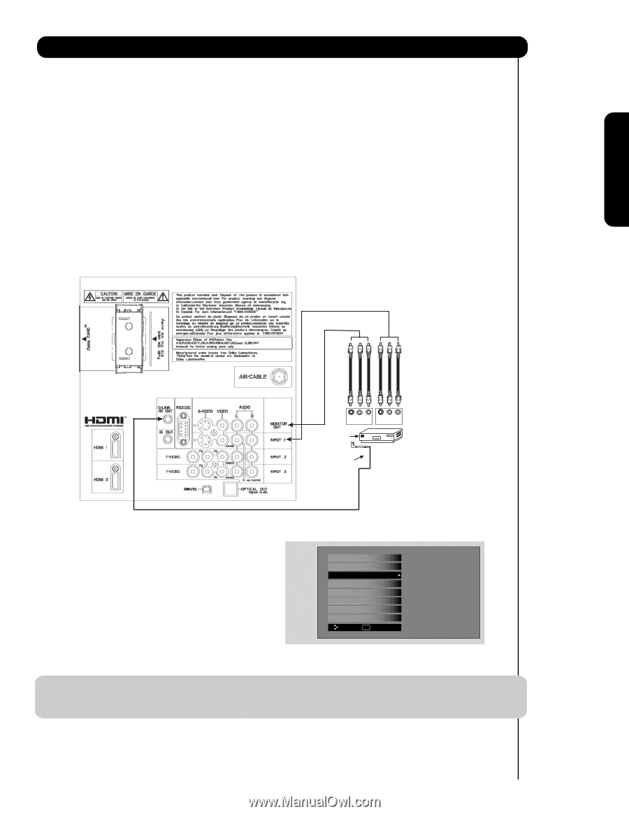
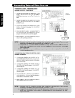
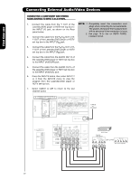
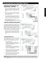
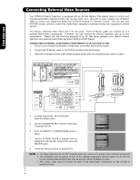
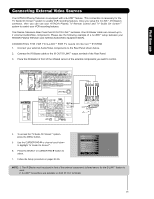
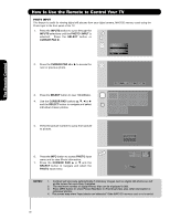
First time use Connecting External Video Sources Your HITACHI Plasma Television is equipped with a G-LINKTM feature. This connection is necessary for the TV Guide On ScreenTM system to enable VCR recording features. Once you setup the G-LINKTM (IR Blaster) connector, then you can use your HITACHI Plasma TV Remote Control and TV Guide On ScreenTM system to control your VCR recording features. The Plasma Television Rear Panel has IR OUT/G-LINKTM terminals. One IR Blaster cable can connect up to 2 external Audio/Video components. Please see the following example of a G-LINKTM setup between your HITACHI Plasma Television and external Audio/Video equipment (VCR). CONNECTING THE VCR TO G-LINKTM FOR TV Guide On ScreenTM SYSTEM 1. Connect your external Audio/Video components to the Rear Panel shown below. 2. Connect the IR Blaster cable to the IR OUT/G-LINKTM output terminal of the Rear Panel. 3. Place the IR Blaster in front of the infrared sensor of the external components you want to control. V L R INPUT V L R OUTPUT Infrared Sensor VCR IR Blaster 4. To access the TV Guide On ScreenTM system, press the MENU button. 5. Use the CURSOR PAD ̄ or channel scroll down to highlight TV Guide On ScreenTM. 6. Press the SELECT or CURSOR PAD ̈ button to select. 7. Follow the Setup procedure on pages 54-56. Video Audio TV Guide On Screen Channel Manager Locks Timers Setup Power Swivel Move SEL Select NOTE: 1. The IR Blaster must be placed in front of the external components infrared sensor for the G-LINKTM feature to work. 2. G-LINKTM connections are available on both IR OUT terminals. 25
-
 1
1 -
2
-
3
-
4
-
5
-
6
-
7
-
8
-
9
-
10
-
11
-
12
-
13
-
14
-
15
-
16
-
17
-
18
-
19
-
 20
20 -
 21
21 -
 22
22 -
 23
23 -
 24
24 -
 25
25 -
 26
26 -
 27
27 -
 28
28 -
 29
29 -
 30
30 -
31
-
32
-
33
-
34
-
35
-
36
-
37
-
38
-
39
-
40
-
41
-
42
-
43
-
44
-
45
-
46
-
47
-
48
-
49
-
50
-
51
-
52
-
53
-
54
-
55
-
56
-
57
-
58
-
59
-
60
-
61
-
62
-
63
-
64
-
65
-
66
-
67
-
68
-
69
-
70
-
71
-
72
-
73
-
74
-
75
-
76
-
77
-
78
-
79
-
80
-
81
-
82
-
83
-
84
-
85
-
86
-
87
-
88
-
89
-
90
-
91
-
92
-
93
-
94
-
95
-
96
-
97
-
98
-
99
-
100
-
101
-
102
-
103
-
104
-
105
-
106
-
107
-
108
-
109
-
110
-
111
-
112
-
113
-
114
-
115
-
116
-
117
-
118
-
119
-
120
-
121
-
122
-
123
-
124
-
125
-
126
-
127
-
128
-
129
-
130
-
131
-
132
-
133
-
134
-
135
-
136
-
137
-
138
-
139
-
140
-
141
-
142
-
143
-
144
-
145
-
146
-
147
-
148
-
149
-
150
-
151
-
152
-
153
-
154
-
155
-
156
-
157
-
158
-
159
-
160
-
161
-
162
-
163
-
164
-
165
-
166
-
167
-
168
-
169
-
170
-
171
-
172
-
173
-
174
-
175
-
176
-
177
-
178
-
179
-
180
-
181
-
182
-
183
-
184
-
185
-
186
-
187
-
188
-
189
-
190
-
191
-
192
 |
 |