Husqvarna AUTOMOWER 415X Owner Manual - Page 13
Introduction - Installation, WARNING, CAUTION, 2 Main components for installation, 3 General
 |
View all Husqvarna AUTOMOWER 415X manuals
Add to My Manuals
Save this manual to your list of manuals |
Page 13 highlights
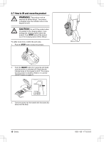
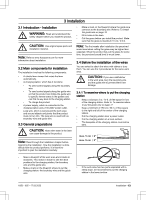
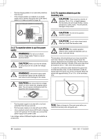
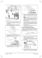
3 Installation 3.1 Introduction - Installation WARNING: Read and understand the safety chapter before you install the product. CAUTION: Use original spare parts and installation material. Note: Refer to www.husqvarna.com for more information about installation. 3.2 Main components for installation The installation involves the following components: • A robotic lawn mower that mows the lawn automatically. • A charging station, which has 3 functions: • To send control signals along the boundary wire. • To send control signals along the guide wire so that the product can follow the guide wire to specific remote areas in the garden and can find its way back to the charging station. • To charge the product. • A power supply, which is connected to the charging station and a 100-240V power outlet. • Loop wire, which is laid around the work area and around objects and plants that the product must not run into. The loop wire is used both as boundary wire and guide wire. 3.3 General preparations • Make a mark on the blueprint where the guide wire connects to the boundary wire. Refer to To install the guide wire on page 18. • Fill in holes in the lawn. • Cut the grass before you install the product. Make sure that the grass is maximum 10 cm / 3.9 in. Note: The first weeks after installation the perceived sound level when cutting the grass may be higher than expected. When the product has cut the grass for some time, the perceived sound level is much lower. 3.4 Before the installation of the wires You can select to attach the wires with stakes or bury them. You can use the 2 procedures for the same work area. CAUTION: If you use a dethatcher in the work area, bury the boundary wire and the guide wire to prevent them from damage. 3.4.1 To examine where to put the charging station • Keep a minimum 3 m / 10 ft. of free space in front of the charging station. Refer to To examine where to put the guide wire on page 17. • Keep a minimum of 150 cm / 60 in. of free space to the right and left of the center of the charging station. • Put the charging station near a power outlet. • Put the charging station on a level surface. • The baseplate of the charging station must not be bent. CAUTION: Holes with water in the lawn can cause damage to the product. Note: Read through the Installation chapter before beginning the installation. How the installation is done affects how the product performs. It is therefore important to plan the installation carefully. max. 5 cm / 2" max. 5 cm / 2" • Make a blueprint of the work area and include all obstacles. This makes it easier to see the ideal positions for the charging station, the boundary wire and the guide wire. • Make a mark on the blueprint where to put the charging station, the boundary wire and the guide wire. • If the work area has two parts separated with a steep slope, we recommend to put the charging station in the lower section. 1650 - 005 - 17.03.2022 Installation - 13
-
 1
1 -
2
-
3
-
4
-
5
-
6
-
7
-
 8
8 -
 9
9 -
 10
10 -
 11
11 -
 12
12 -
 13
13 -
 14
14 -
 15
15 -
 16
16 -
 17
17 -
 18
18 -
19
-
20
-
21
-
22
-
23
-
24
-
25
-
26
-
27
-
28
-
29
-
30
-
31
-
32
-
33
-
34
-
35
-
36
-
37
-
38
-
39
-
40
-
41
-
42
-
43
-
44
-
45
-
46
-
47
-
48
-
49
-
50
-
51
-
52
 |
 |
