Husqvarna AUTOMOWER 415X Owner Manual - Page 17
Installation of the product
 |
View all Husqvarna AUTOMOWER 415X manuals
Add to My Manuals
Save this manual to your list of manuals |
Page 17 highlights
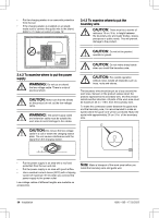
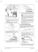
B A • Put the boundary wire around the secondary area (B) to make an island. Refer to To make an island on page 16. Note: The boundary wire must be put as 1 loop around all of the work area (A + B). • If the work area has a passage (B) with no guide wire installed, the minimum distance between the boundary wires is 2 m / 6.5 ft. With a guide wire installed through the passage, the minimum distance between the boundary wires is 60 cm / 24 in. • If the work area has areas which are connected by a narrow passage (B), you can set the product to first follow and then leave the guide wire after a certain distance (C). The settings can be changed in GPS Assisted Navigation, Lawn Coverage and Systematic Passage Mowing on page 24. • If the work area includes a secondary area (D), refer to Secondary area on page 31. Put the product in the secondary area and select Secondary area mode. D Note: When the product cuts grass in the secondary area, the Secondary area mode must be selected. Refer to Secondary area on page 31. 3.4.4 To examine where to put the guide wire • Put the guide wire in a line at a minimum of 2 m / 6.5 ft. in front of the charging station. • Make as much free area as possible to the left of the guide wire when facing the charging station. • Put the guide wire minimum 30 cm / 12 in. from the boundary wire. • Do not make sharp bends when you install the guide wire. A B C 135º 90º 135º • If the work area has a slope, put the guide wire diagonally across the slope. 3.4.5 Work area examples • If the charging station is put in a small area (A), make sure that the distance to the boundary wire is at a minimum 3 m / 10 ft. in front of the charging station. 3.5 Installation of the product 3.5.1 Installation tools • Hammer/plastic mallet: To simplify putting the stakes into the ground. • Edge cutter/straight spade: To bury the boundary wire. • Combination pliers: For cutting the boundary wire and pressing the connectors together. • Adjustable plier: For pressing the couplers together. 1650 - 005 - 17.03.2022 Installation - 17
-
 1
1 -
2
-
3
-
4
-
5
-
6
-
7
-
8
-
9
-
10
-
11
-
 12
12 -
 13
13 -
 14
14 -
 15
15 -
 16
16 -
 17
17 -
 18
18 -
 19
19 -
 20
20 -
 21
21 -
 22
22 -
23
-
24
-
25
-
26
-
27
-
28
-
29
-
30
-
31
-
32
-
33
-
34
-
35
-
36
-
37
-
38
-
39
-
40
-
41
-
42
-
43
-
44
-
45
-
46
-
47
-
48
-
49
-
50
-
51
-
52
 |
 |
