IBM QS21 Service Guide - Page 66
information
 |
UPC - 883436016940
View all IBM QS21 manuals
Add to My Manuals
Save this manual to your list of manuals |
Page 66 highlights
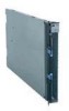
Blade Cover Blade-Cover Release Bezel-Assembly Release Blade-Cover Release Bezel-Assembly Release Control-Panel Cable Control-Panel Connector Bezel Figure 23. Reinstalling the front bezel assembly Complete the following steps to install the blade server front bezel assembly: 1. Read the safety information beginning on page vii and "Installation guidelines" on page 29. 2. Connect the control panel cable to the control panel connector on the system board assembly. 3. Carefully slide the front bezel assembly onto the blade server, as shown in Figure 23, until it clicks into place. Note: Make sure that you do not pinch any cables when you reinstall the front bezel assembly. 48 BladeCenter QS21 Type 0792: Problem Determination and Service Guide
-
 1
1 -
2
-
3
-
4
-
5
-
6
-
7
-
8
-
9
-
10
-
11
-
12
-
13
-
14
-
15
-
16
-
17
-
18
-
19
-
20
-
21
-
22
-
23
-
24
-
25
-
26
-
27
-
28
-
29
-
30
-
31
-
32
-
33
-
34
-
35
-
36
-
37
-
38
-
39
-
40
-
41
-
42
-
43
-
44
-
45
-
46
-
47
-
48
-
49
-
50
-
51
-
52
-
53
-
54
-
55
-
56
-
57
-
58
-
59
-
60
-
 61
61 -
 62
62 -
 63
63 -
 64
64 -
 65
65 -
 66
66 -
 67
67 -
 68
68 -
 69
69 -
 70
70 -
 71
71 -
72
-
73
-
74
-
75
-
76
-
77
-
78
-
79
-
80
-
81
-
82
-
83
-
84
-
85
-
86
-
87
-
88
-
89
-
90
-
91
-
92
-
93
-
94
-
95
-
96
-
97
-
98
-
99
-
100
-
101
-
102
-
103
-
104
-
105
-
106
-
107
-
108
-
109
-
110
-
111
-
112
-
113
-
114
-
115
-
116
-
117
-
118
-
119
-
120
-
121
-
122
-
123
-
124
-
125
-
126
-
127
-
128
-
129
-
130
-
131
-
132
-
133
-
134
-
135
-
136
-
137
-
138
-
139
-
140
-
141
-
142
-
143
-
144
 |
 |

Complete
the
following
steps
to
install
the
blade
server
front
bezel
assembly:
1.
Read
the
safety
information
beginning
on
page
vii
and
“Installation
guidelines”
on
page
29.
2.
Connect
the
control
panel
cable
to
the
control
panel
connector
on
the
system
board
assembly.
3.
Carefully
slide
the
front
bezel
assembly
onto
the
blade
server,
as
shown
in
Figure
23,
until
it
clicks
into
place.
Note:
Make
sure
that
you
do
not
pinch
any
cables
when
you
reinstall
the
front
bezel
assembly.
Bezel-Assembly
Release
Bezel-Assembly
Release
Bezel
Blade Cover
Control-Panel
Connector
Control-Panel
Cable
Blade-Cover
Release
Blade-Cover
Release
Figure
23.
Reinstalling
the
front
bezel
assembly
48
BladeCenter
QS21
Type
0792:
Problem
Determination
and
Service
Guide