IBM QS21 Service Guide - Page 67
Closing, blade, server, cover, Input/output, connectors, devices
 |
UPC - 883436016940
View all IBM QS21 manuals
Add to My Manuals
Save this manual to your list of manuals |
Page 67 highlights
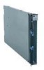
Closing the blade server cover Important: The blade server cannot be inserted into the BladeCenter unit until the cover is installed and closed. Do not attempt to override this protection. Cover pins Cover release Cover release Figure 24. Closing the blade server cover Complete the following steps to close the blade server cover: 1. Read the safety information beginning on page vii and "Installation guidelines" on page 29. 2. If you removed the front bezel assembly, replace it now. See "Installing the front bezel assembly" on page 47 for instructions, and Figure 24. 3. Lower the cover so that the slots at the rear slide down onto the pins at the rear of the blade server, as shown Figure 24. Before closing the cover, make sure that all components are installed and seated correctly and that you have not left loose tools or parts inside the blade server. 4. Carefully close the cover as shown in Figure 24 until it clicks into place. Input/output connectors and devices The BladeCenter unit contains the input/output connectors that are available to the blade server. See the documentation that comes with the BladeCenter unit for information about the input/output connectors. Chapter 4. Installing and removing replaceable units 49
-
 1
1 -
2
-
3
-
4
-
5
-
6
-
7
-
8
-
9
-
10
-
11
-
12
-
13
-
14
-
15
-
16
-
17
-
18
-
19
-
20
-
21
-
22
-
23
-
24
-
25
-
26
-
27
-
28
-
29
-
30
-
31
-
32
-
33
-
34
-
35
-
36
-
37
-
38
-
39
-
40
-
41
-
42
-
43
-
44
-
45
-
46
-
47
-
48
-
49
-
50
-
51
-
52
-
53
-
54
-
55
-
56
-
57
-
58
-
59
-
60
-
61
-
 62
62 -
 63
63 -
 64
64 -
 65
65 -
 66
66 -
 67
67 -
 68
68 -
 69
69 -
 70
70 -
 71
71 -
 72
72 -
73
-
74
-
75
-
76
-
77
-
78
-
79
-
80
-
81
-
82
-
83
-
84
-
85
-
86
-
87
-
88
-
89
-
90
-
91
-
92
-
93
-
94
-
95
-
96
-
97
-
98
-
99
-
100
-
101
-
102
-
103
-
104
-
105
-
106
-
107
-
108
-
109
-
110
-
111
-
112
-
113
-
114
-
115
-
116
-
117
-
118
-
119
-
120
-
121
-
122
-
123
-
124
-
125
-
126
-
127
-
128
-
129
-
130
-
131
-
132
-
133
-
134
-
135
-
136
-
137
-
138
-
139
-
140
-
141
-
142
-
143
-
144
 |
 |
