Icom IC-M510 Instruction Manual - Page 113
MBF-7 installation
 |
View all Icom IC-M510 manuals
Add to My Manuals
Save this manual to your list of manuals |
Page 113 highlights
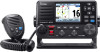
CONNECTIONS AND MAINTENANCE 12 ■ MBF-7 installation The optional MBF-7 FlUsh moUnt kit is for mounting the transceiver to a flat surface (less than 20 mm thick), such as an instrument panel. 1 NOTE: Install the transceiver and/or microphone more than 1 meter from the vessel's 2 magnetic navigation compass. 1. Using the template on page 114, carefully cut a 3 hole in the instrument panel, or wherever you plan to mount the transceiver. 4 2. Slide the transceiver through the hole, as shown on the right. 5 6 7 3. Attach the 2 bolts (5 × 8 mm) and spacer supplied 8 with the MBF-7 to both sides of the transceiver. 9 10 11 12 13 4. Insert the clamps between the supplied bolts and the instrument control panel, and then tighten the supplied bolts so that the clamps press firmly against Supplied bolt the inside of the instrument control panel. (Torque: 2 N•m) L Make sure that the clamps align parallel to the transceiver body. Clamp 4 4 14 15 16 17 18 5. Tighten the end bolts on the clamps (rotate clockwise). 5 End bolt 100
-
 1
1 -
2
-
3
-
4
-
5
-
6
-
7
-
8
-
9
-
10
-
11
-
12
-
13
-
14
-
15
-
16
-
17
-
18
-
19
-
20
-
21
-
22
-
23
-
24
-
25
-
26
-
27
-
28
-
29
-
30
-
31
-
32
-
33
-
34
-
35
-
36
-
37
-
38
-
39
-
40
-
41
-
42
-
43
-
44
-
45
-
46
-
47
-
48
-
49
-
50
-
51
-
52
-
53
-
54
-
55
-
56
-
57
-
58
-
59
-
60
-
61
-
62
-
63
-
64
-
65
-
66
-
67
-
68
-
69
-
70
-
71
-
72
-
73
-
74
-
75
-
76
-
77
-
78
-
79
-
80
-
81
-
82
-
83
-
84
-
85
-
86
-
87
-
88
-
89
-
90
-
91
-
92
-
93
-
94
-
95
-
96
-
97
-
98
-
99
-
100
-
101
-
102
-
103
-
104
-
105
-
106
-
107
-
 108
108 -
 109
109 -
 110
110 -
 111
111 -
 112
112 -
 113
113 -
 114
114 -
 115
115 -
 116
116 -
 117
117 -
 118
118 -
119
-
120
-
121
-
122
-
123
-
124
-
125
-
126
-
127
-
128
-
129
-
130
-
131
-
132
 |
 |
