Intel SHG2 Product Guide
Intel SHG2 - Server Board Motherboard Manual
 |
UPC - 735858152891
View all Intel SHG2 manuals
Add to My Manuals
Save this manual to your list of manuals |
Intel SHG2 manual content summary:
- Intel SHG2 | Product Guide - Page 1
Intel® Server Board SHG2 Product Guide A Guide for Technically Qualified Assemblers of Intel® Identified Subassemblies/Products Order Number: A90327-003 - Intel SHG2 | Product Guide - Page 2
or warranties relating to fitness for a particular purpose, merchantability, or infringement of any patent, copyright or other intellectual property right. Intel products are not designed, intended or authorized for use in any medical, life saving, or life sustaining applications or for any other - Intel SHG2 | Product Guide - Page 3
Server Board Features ...9 Back Panel Connectors 10 Server Board Connector and Component Locations 11 Processor ...12 Memory ...12 Add-in Board Connectors ...13 Video ...13 SCSI Controller ...14 Modular RAID Capable PCI-X Slot 6 14 IDE Controller...14 USB Interface ...14 Network Controllers - Intel SHG2 | Product Guide - Page 4
Update Diskette 76 Updating the BMC Firmware 76 Recovering the BMC Firmware 77 Updating the FRU/SDR Files 77 Making a FRU/SDR File Update Diskette 77 Updating the FRU/SDR Files 77 Using the Adaptec SCSI Utility 78 Running the SCSI Utility 78 iv Intel Server Board SHG2 Product Guide - Intel SHG2 | Product Guide - Page 5
Activity Light Does Not Light 84 Cannot Connect to a Server 84 Problems with Network 85 PCI Installation Tips...85 Problems with Application Software 86 Bootable CD-ROM Is Not Detected 86 6 Getting Help ...87 7 Technical Reference Server Board Jumpers...89 Enabling PCI-X on Slot 6 and Disabling - Intel SHG2 | Product Guide - Page 6
Server Board 35 21. Routing Cables ...36 22. Routing the Floppy and USB Cables 37 23. Routing the Floppy and ICMB Cables 37 24. Installing the Serial B Cable 38 25. Making Back Panel Connections 39 26. Installing Memory ...45 27. Installing the Retention Brackets 52 28. Opening Socket Lever - Intel SHG2 | Product Guide - Page 7
Tables 1. Server Board Features 9 2. Video Modes ...13 3. Software Security Features 19 4. Configuration Utilities 55 5. Hot Keys ...55 6. Beep Codes ...81 7. Configuration Jumper (CN43 89 8. Configuration Jumper (CN27 90 9. Configuration Jumper (CN53 90 Contents vii - Intel SHG2 | Product Guide - Page 8
viii Intel Server Board SHG2 Product Guide - Intel SHG2 | Product Guide - Page 9
Server Board Features Table 1. Server Board Features Feature Description Processor Up to two 1.8 GHz to 2.4 GHz Intel® Xeon™ processors with 512K cache support packaged in a 603-pin micro Pin-Grid Array (PGA) System Bus Frequency 400 MHz Front Side Bus Memory (DRAM) Six 72-bit sockets - Intel SHG2 | Product Guide - Page 10
H NIC2 (Gbit) C Mouse I NIC1 (10/100) D Keyboard J ICMB/External SCSI Connector Knockout* E Parallel Port K Serial B Knockout* F Serial A * Intel SC5200 Base chassis shown here. Item may be different on your chassis. Figure 1. Back Panel Connectors 10 Intel Server Board SHG2 Product Guide - Intel SHG2 | Product Guide - Page 11
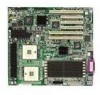
Server Board Connector and Component Locations II JJ KK LL HH A GG B FF EE DD CC BB AA Z Y C D E F H J G I K L M N O P Q X W V U T SR A Primary Processor Socket (CPU1) B CPU2 Fan C Secondary Processor Socket (CPU2) D Front Panel USB E Serial B F Jumper Block CN27 G System Fan 5 H - Intel SHG2 | Product Guide - Page 12
must be installed in the CPU1 socket, which is the socket closest to the corner of the server board. For a complete list of supported processors, see: http://support.intel.com/support/motherboards/server/SHG2 Memory The Intel Server Board SHG2 contains six 184-pin DIMM sockets. Memory is partitioned - Intel SHG2 | Product Guide - Page 13
the onboard SCSI controller using BIOS Setup. See page 57 for more information on using BIOS Setup. The default operation of this connector (slot 6) is PCI 64-bit/66 MHz operation. Video The system has an integrated ATI Rage XL 32-bit high-performance SVGA subsystem that supports the following - Intel SHG2 | Product Guide - Page 14
://support.intel.com/support/motherboards/server/SHG2 IDE Controller The system includes a dual-channel enhanced IDE 32-bit interface controller for intelligent disk drives with disk controller electronics onboard. The controller has two connectors, Primary and Secondary, located on the system board - Intel SHG2 | Product Guide - Page 15
direct interface to the PCI-X bus. It is compliant with the PCI Local Bus Specification, Revision 2.2. It also supports the PCI-X extension to the PCI Local Bus, Revision 1.0a. ✏ NOTE If you install a 32/64-bit, 33/66 MHz PCI card in Add-in card slots 1 or 2, you will slow the PCI-X bus to - Intel SHG2 | Product Guide - Page 16
configured for ALB also provide the benefits of AFT. Receive rates remain at 100 Mbps. To use ALB, you must have two, three, or four server adapters installed in your server or workstation and linked to the same network switch. 16 Intel Server Board SHG2 Product Guide - Intel SHG2 | Product Guide - Page 17
, Intel® Server Management software monitors the system intrusion switch. Security with Mechanical Locks and Monitoring If installed, you can activate the chassis intrusion alarm switch. When the side door is opened, the switch transmits an alarm signal to the server board, where BMC firmware and - Intel SHG2 | Product Guide - Page 18
password if you want to enter BIOS Setup or the SSU and have access to all of the options. • May enter either password to boot the server if Password on Boot is enabled in either the BIOS Setup or SSU. • May enter either password to exit secure mode. 18 Intel Server Board SHG2 Product Guide - Intel SHG2 | Product Guide - Page 19
the server and the operating system will run, but you must enter the user password to use the keyboard or mouse. • You cannot turn off system power or reset the server from the front panel switches. Secure mode has no effect on functions enabled via the Server Manager Module or power control via - Intel SHG2 | Product Guide - Page 20
Chapter 7). To control access to using the system, set a server fully boots. If secure mode is enabled and the "Secure Boot Mode" option is also enabled, the server will fully boot but will require a password before accepting any keyboard or mouse input. 20 Intel Server Board SHG2 Product Guide - Intel SHG2 | Product Guide - Page 21
2 Server Board Installation Tools and Supplies Needed • Phillips† (cross head) screwdriver (#1 bit and #2 bit) • Flat blade screwdriver • Antistatic of your end system product may require additional EMC compliance testing. For more information, please contact your local Intel Representative. See - Intel SHG2 | Product Guide - Page 22
servers that will be installed in board damage, your system must meet the following minimum requirements. For more information on supported processors and qualified memory and chassis components, see: http://support.intel.com/support/motherboards/server/SHG2 Processor A minimum of one 1.8 GHz Intel - Intel SHG2 | Product Guide - Page 23
memory Remove the access cover Install the I/O shield Rearrange the standoffs Install the server board Connect cables to the server board Finish setting up your chassis Where the information is located This guide This guide This guide Your chassis manual This guide This guide This guide This guide - Intel SHG2 | Product Guide - Page 24
I/O Shield 1. Remove the backing from the label included with your server board. 2. Press the label onto the outside face of the I/O shield. USB 1 2 3 KMYOBUDSE PARALLEL (GNbIiCt)2 (10N/1I0C01) OM14360 Figure 4. Attaching the Label to the I/O Shield 24 Intel Server Board SHG2 Product Guide - Intel SHG2 | Product Guide - Page 25
Installing the I/O Shield 1. Position one edge so that the dotted groove is outside the chassis wall, and the lip of the it into the opening until it is seated. Make sure the I/O shield snaps into place all the way around. Figure 5. Installing the I/O Shield OM14361 Server Board installation 25 - Intel SHG2 | Product Guide - Page 26
with the server board. Contact your sales representative or dealer for a current list of approved memory modules. Check the Intel Customer Support website for the latest tested memory list: http://support.intel.com/support/motherboards/server/SHG2 26 Intel Server Board SHG2 Product Guide - Intel SHG2 | Product Guide - Page 27
that socket levers are securely latched. DIMMs must be populated in identical pairs. 2 1A 3 1 1B OM13205 Figure 7. Installing Memory Configuring Chassis Standoffs If your chassis does not have standoffs placed as shown below, you must rearrange them so they match the holes in the server board - Intel SHG2 | Product Guide - Page 28
Installing the Server Board 1. Place the board into the chassis, making sure that the back panel I/O shield openings and chassis standoffs align correctly. 2. Attach the board with the screws included with your chassis at the ten locations marked below. For the Intel SC5200 chassis, these screws are - Intel SHG2 | Product Guide - Page 29
(s) CAUTIONS If only one processor is to be used, it must be installed in the Processor Socket labeled CPU1, which is the socket closest to the corner of the server board. If you are adding a second processor to your system, you must verify that the second processor is identical in speed to the - Intel SHG2 | Product Guide - Page 30
that the secondary processor socket is oriented so that the processor pins are rotated 180° relative to the primary processor socket. A B OM14365 A. Alignment Triangle Mark B. Alignment Triangle Cutout Figure 11. Opening Socket Lever and Attaching Processor 30 Intel Server Board SHG2 Product Guide - Intel SHG2 | Product Guide - Page 31
5. Apply thermal grease to the processor as shown. OM14366 Figure 12. Applying Thermal Grease 6. Align the heat sink with the retention brackets and place heat sink on the processor. OM14367 Figure 13. Aligning the Heat Sink Server Board installation 31 - Intel SHG2 | Product Guide - Page 32
the Processor Wind Tunnel The following instructions apply to the Intel SC5200 Base Server Chassis and reference chassis installations. If you are installing your server board in the Intel SC5200 Hot-Swap, Redundant Power Server Chassis, DO NOT install the processor wind tunnel. The ducting - Intel SHG2 | Product Guide - Page 33
Fan to the Air Intake Assembly CAUTION To ensure proper system cooling, the heat sink fan must be installed as shown in Figure 18 and the air intake fan assembly must be attached to the side of the processor / wind tunnel assembly nearest to the front of the chassis. Server Board installation 33 - Intel SHG2 | Product Guide - Page 34
assembly to the side of the heat sink wind tunnel closest to the front of the chassis. a. Press both sides of the air intake section to CPU Fan cable(s). See the next section "Making Connections to the Server Board" for fan connector location information. 34 Intel Server Board SHG2 Product Guide - Intel SHG2 | Product Guide - Page 35
Z. PCI 32-bit/33 MHz AA. PCI-X 64-bit/100 MHz BB. System Fan 1 CC. System Fan 2 DD. ICMB EE. NIC1 (10/100) FF. NIC2 (Gbit) GG. System I/O connectors HH. DIMMs II. Main Power JJ. Aux Sig KK. +12 V CPU Power LL. CPU1 Fan Figure 20. Making Connections to the Server Board Server Board installation 35 - Intel SHG2 | Product Guide - Page 36
below. IDE or SCSI Cables Cables that connect to devices in the lower device bays should be routed around the epac system fan carrier as shown below. 1. Route cables as shown. 2. Replace the top half of the epac. Figure 21. Routing Cables OM14556 36 Intel Server Board SHG2 Product Guide - Intel SHG2 | Product Guide - Page 37
floppy drive and front panel cables as shown. A B A. Front Panel Cable B. Floppy Diskette Cable OM14376 Figure 22. Routing the Floppy and Front Panel Cables Cable Routing - Intel SC5200 Hot-Swap, Location OM14377 Figure 23. Routing the Floppy and ICMB Cables Server Board installation 37 - Intel SHG2 | Product Guide - Page 38
the other end to the Serial B connector located on your server baseboard. See "Making Connections to the Server Board" on page 35 for the Serial B connector location. A B OM14557 A. Chassis Back Panel Cutout B. Screw Figure 24. Installing the Serial B Cable 38 Intel Server Board SHG2 Product Guide - Intel SHG2 | Product Guide - Page 39
C Mouse D Keyboard E Parallel Port G Video H NIC2 (Gbit) I NIC1 (10/100) J ICMB/External SCSI Connector Knockout* K Serial B Knockout* F Serial A * Intel SC5200 Base chassis shown here. Item may be different on your chassis. Figure 25. Making Back Panel Connections Server Board installation 39 - Intel SHG2 | Product Guide - Page 40
& User Guide located in the "ISM/Docs" folder on the Intel Server Management CD-ROM. SMaRT Tool and ISM Console may only be installed on a system running a Microsoft Windows operating system. Note: Prior to installation, uninstall any previous version of Intel Server Control. Installing a Service - Intel SHG2 | Product Guide - Page 41
Operating System Install your operating system now. Installing Intel Server Management You can install Intel Server Management on a local server or on a remote workstation that is used to manage a LAN/WAN. 1. Insert the Intel Server Management CD into the system's CD-ROM. 2. Click Install Server - Intel SHG2 | Product Guide - Page 42
Tool may only be installed on a system running a Microsoft Windows operating system. To download the SHG2 SC5200 server system module for SMaRT Tool, you must have Internet access. 1. Insert the Intel Server Board SHG2 Resource CD into the system's CD-ROM drive. 2. Click on Intel SMaRT Tool in the - Intel SHG2 | Product Guide - Page 43
• Phillips (cross head) screwdriver (#1 bit and #2 bit) • Antistatic wrist strap and conductive foam pad (recommended) Cautions These warnings and cautions apply throughout this chapter. Only a technically qualified person should configure the server board. CAUTIONS System power on/off: The power - Intel SHG2 | Product Guide - Page 44
with the server board. Contact your sales representative or dealer for a current list of approved memory modules. Check the Intel Customer Support website for the latest tested memory list: http://support.intel.com/support/motherboards/server/SHG2 44 Intel Server Board SHG2 Product Guide - Intel SHG2 | Product Guide - Page 45
considerations). For exact information about processor interchangeability, contact your customer service representative or visit the Intel Customer Support website: http://support.intel.com/support/motherboards/server/SHG2 ESD and handling processors: Reduce the risk of electrostatic discharge (ESD - Intel SHG2 | Product Guide - Page 46
system or chassis documentation for instructions). 4. Install the retention brackets for the primary processor by inserting the retention brackets (A) and tightening the four retention screws. The primary processor socket is located nearest to the corner of the server board. If installing a second - Intel SHG2 | Product Guide - Page 47
labeled CPU2.) 6. Align the pins of the processor with the socket, and insert the processor into the socket. Lower the socket lever completely. ✏ NOTE When installing a second processor, note that the secondary processor socket is oriented so that the processor pins are rotated 180° relative to - Intel SHG2 | Product Guide - Page 48
7. Apply thermal grease to the processor as shown. OM14366 Figure 29. Applying Thermal Grease 8. Align the heat sink with the retention brackets and place heat sink on the processor. OM14367 Figure 30. Aligning the Heat Sink 48 Intel Server Board SHG2 Product Guide - Intel SHG2 | Product Guide - Page 49
the Processor Wind Tunnel The following instructions apply to the Intel SC5200 Base Server Chassis and reference chassis installations. If you are installing your server board in the Intel SC5200 Hot-Swap, Redundant Power Server Chassis, DO NOT install the processor wind tunnel. The ducting - Intel SHG2 | Product Guide - Page 50
Air Intake Assembly CAUTION To ensure proper system cooling, the heat sink fan must be installed as shown in Figure 34 and the air intake fan assembly must be attached to the side of the processor / wind tunnel assembly nearest to the front of the chassis. 50 Intel Server Board SHG2 Product Guide - Intel SHG2 | Product Guide - Page 51
fan assembly to the side of the heat sink wind tunnel closest to the front of the chassis. a. Press both sides of the air intake section to bend and Exhaust 5. Attach CPU Fan cable(s). See "Making Connections to the Server Board" on page 35 for fan connector location information. Upgrading 51 - Intel SHG2 | Product Guide - Page 52
enligt fabrikantens instruktion. VAROITUS Paristo voi räjähtää, jos se on virheellisesti asennettu. Vaihda paristo ainoastaan laitevalmistajan suosittelemaan tyyppiin. Hävitä käytetty paristo valmistajan ohjeiden mukaisesti. 52 Intel Server Board SHG2 Product Guide - Intel SHG2 | Product Guide - Page 53
on the screwdriver to lift the battery. 4. Remove the battery from its socket. 5. Dispose of the battery according to local ordinance. 6. Remove the new the correct polarity, insert it in the battery socket. 7. Close the chassis. 8. Run BIOS Setup to restore the configuration settings to the RTC - Intel SHG2 | Product Guide - Page 54
54 Intel Server Board SHG2 Product Guide - Intel SHG2 | Product Guide - Page 55
. Adaptec SCSI Utility Used to configure or view the settings of the SCSI host adapters and onboard SCSI devices in the server. Page 57 58 69 73 76 78 Hot Keys Use the keyboard's numeric pad to enter numbers and symbols. Table 5. Hot Keys To do this: Clear memory and reload the operating system - Intel SHG2 | Product Guide - Page 56
as the message appears. Note the screen display and write down the beep code you hear; this information is useful for your service representative. For a listing of beep codes and error messages that POST can generate, see the "Monitoring POST" on page 81. 56 Intel Server Board SHG2 Product Guide - Intel SHG2 | Product Guide - Page 57
server, after POST completes the memory test • When you reboot the server by pressing while at the DOS operating system prompt • When you have moved the CMOS jumper on the server board condition, the BIOS will load default values for CMOS and attempt to boot. Configuration Software - Intel SHG2 | Product Guide - Page 58
Diskettes by Device/Function > System Setup Utility. 3. Follow the instructions displayed. Alternatively, if you have a workstation with the Microsoft Windows operating system, you can insert the CD into that system and create the diskettes on that system. 58 Intel Server Board SHG2 Product Guide - Intel SHG2 | Product Guide - Page 59
The SSU supports ROM-DOS version 6.22. The SSU will not operate from a "DOS box" running under an operating system such as Windows. To start the SSU: 1. Start the SSU using one of the following methods: From diskettes: Insert the first SSU diskette in drive A and boot the server from the diskette - Intel SHG2 | Product Guide - Page 60
a user password and an admin password. On some systems, you must set an admin password before you can set a user password. On other systems, the passwords are independent. You can set the same passwords and security options by using BIOS Setup (page 57). 60 Intel Server Board SHG2 Product Guide - Intel SHG2 | Product Guide - Page 61
SSU and the system BIOS. All changes to the user password take effect immediately. To change or clear the user password: 1. From the SSU Main window, choose Security. combination that can be used to put the server into secure mode. • Secure Mode Timer: If no keyboard or mouse activity occurs during - Intel SHG2 | Product Guide - Page 62
FRU data to a file. • Properties: Displays the number of FRU devices in the system and the number being displayed. Only FRU devices with valid FRU areas are displayed. • Reload: Refreshes the display by reading the current FRU entries from the server. 62 Intel Server Board SHG2 Product Guide - Intel SHG2 | Product Guide - Page 63
memory. The SDR Manager window download the updates from the Intel support website: http://support.intel.com/support/motherboards/server/SHG2 Updating the BIOS To update the BIOS: 1. Download the update from the Intel support website. 2. From the SSU Main window, choose System Update. (System Update - Intel SHG2 | Product Guide - Page 64
stored in the file. Saving a Configuration To save the system configuration: 1. From the SSU Main window, choose Config Save/Restore. (Configuration Save/Restore is available only in Expert mode.) 2. Click Save To File and specify a filename and location. 64 Intel Server Board SHG2 Product Guide - Intel SHG2 | Product Guide - Page 65
Interface Control (PIC) software to configure an email address to receive alerts. For more information on installing Intel Server Management (ISM) software, see page 40. For more information on configuring email alerts using the PIC, see the Installation & User Guide located on the ISM CD-ROM - Intel SHG2 | Product Guide - Page 66
assigned by the DHCP (dynamic host control protocol) server on the network. The Host, Gateway, and Subnet Mask boxes in the dialog are ignored. • Static: assign the IP address for the server using the Host, Gateway, and Subnet Mask boxes in the dialog. 66 Intel Server Board SHG2 Product Guide - Intel SHG2 | Product Guide - Page 67
Alert. 14. Click Save to save the changes. 15. Click Close to return to the PEM window. Managing the Server Remotely You can set up the server to so that you can connect to it from a remote client system to perform management tasks. You can make the connection over a LAN or by using a modem - Intel SHG2 | Product Guide - Page 68
Main window, choose Platform Event Manager (PEM). 2. In the PEM window, click system can initiate a connection, but cannot perform control operations such as power down, reset, or front panel NMI. • Disabled: the remote system has full control of the server. 68 Intel Server Board SHG2 Product Guide - Intel SHG2 | Product Guide - Page 69
Click Close to return to the PEM window. FRUSDR Load Utility The Field Replacement Unit (FRU) and Sensor Data Record (SDR) Load Utility is a DOS-based program used to update the server management subsystem's product level FRU, SDR, and the SM BIOS (SMB) nonvolatile storage components (EEPROMs). The - Intel SHG2 | Product Guide - Page 70
is displayed. Each area represents a sensor; one sensor for each instrumented device in the server. If the given display function fails because of an inability to parse the data present or a hardware failure, the utility displays an error message and exits. 70 Intel Server Board SHG2 Product Guide - Intel SHG2 | Product Guide - Page 71
the field is a number. Each SM BIOS area displayed is headed with the SM BIOS area designated name. Each field has by the field in ASCII or as a number. The Board, Chassis, and Product FRU areas end with an END file has all the possible SDRs for the system. These records may need to be filtered - Intel SHG2 | Product Guide - Page 72
-booted. Cleaning Up and Exiting If an update was successfully performed, the utility displays an appropriate message and then exits with a DOS exit code of zero. If the utility fails, it immediately exits with an error message and a non-zero DOS exit code. 72 Intel Server Board SHG2 Product Guide - Intel SHG2 | Product Guide - Page 73
from the Intel Customer Support website: http://support.intel.com/support/motherboards/server/SHG2 ✏ NOTE Please review the instructions distributed with the upgrade utility before attempting a BIOS upgrade. This upgrade utility allows you to: • Upgrade the BIOS in flash memory • Update the language - Intel SHG2 | Product Guide - Page 74
erratically. ✏ NOTE You may encounter a CMOS Checksum error or other problem after reboot. Try shutting down the system and booting up again. CMOS checksum errors require that you enter Setup, check your settings, save your settings, and exit Setup. 74 Intel Server Board SHG2 Product Guide - Intel SHG2 | Product Guide - Page 75
corruption, the following procedure may be used to perform a BIOS recovery boot. 1. Prepare a bootable floppy diskette containing the BIOS recovery files for the SHG2 server board obtained from Intel's web sites. 2. Power off the system, unplug the power cord, and remove the chassis cover. 3. Add - Intel SHG2 | Product Guide - Page 76
guideline. Please follow the specific instructions described in the release notes. 1. Prepare a bootable floppy diskette containing the updated BMC firmware files for the SHG2 Server Board obtained from: http://support.intel.com/support/motherboards/server/SHG2 2. Insert the BMC Firmware floppy - Intel SHG2 | Product Guide - Page 77
: http://support.intel.com/support/motherboards/server/SHG2 Making a FRU/SDR File Update Diskette 1. Place a formatted diskette in the diskette drive. 2. Extract the contents of the SHG2 FRU/SDR file onto the diskette. Making the Update Diskette Bootable 1. Use a DOS or Windows 95 system to create - Intel SHG2 | Product Guide - Page 78
those of other devices in the server Running the SCSI Utility 1. When this message appears on the video monitor: Press Ctrl-A to run SCSI Utility... 2. Press to run this utility. When it appears, choose the host adapter that you want to configure. 78 Intel Server Board SHG2 Product Guide - Intel SHG2 | Product Guide - Page 79
? q Are all device drivers properly installed? q Are the configuration settings made in BIOS Setup correct? q Is the operating system properly loaded? Refer to the operating system documentation. q Did you press the system power on/off switch on the front panel to turn the server on (power on light - Intel SHG2 | Product Guide - Page 80
your power line. If you are experiencing any of the above symptoms that might indicate voltage spikes on the power line, you may want to install a surge suppressor between the power outlet and the system power cord. 80 Intel Server Board SHG2 Product Guide - Intel SHG2 | Product Guide - Page 81
1-3-1-1 Test DRAM refresh 1-3-1-3 Test 8742 Keyboard Controller 1-3-3-1 Auto size DRAM, system BIOS stops execution here if the BIOS does not detect any usable memory DIMMs 1-3-4-1 Base RAM failure; BIOS stops execution here if entire memory is bad 2-1-2-3 Check ROM copyright notice - Intel SHG2 | Product Guide - Page 82
If you cannot correct the problem, contact your service representative or authorized dealer for help. Power Light Does Not Light Check the following: q Is the system operating normally? If so, the power LED may be defective or the cable from the front panel to the server board is loose. q Are there - Intel SHG2 | Product Guide - Page 83
the video monitor signal cable properly installed? q Is the onboard video controller enabled? If you are using an add-in video controller board, do the following: 1. Verify that the video controller board is fully seated in the server board connector. 2. Reboot the system for changes to take effect - Intel SHG2 | Product Guide - Page 84
a problem with the diskette drive, server board, or drive signal cable. Contact your service representative or authorized dealer for help. Hard Disk Drive Activity Light Does Not Light The hard disk drive activity light is not connected to the SHG2 server board. 84 Intel Server Board SHG2 Product - Intel SHG2 | Product Guide - Page 85
on crossover cables). q Check the network controller LEDs that are visible through an opening at the system back panel. Problems with Network The server hangs when the drivers are loaded. q Change the PCI BIOS interrupt settings. Try the "PCI Installation Tips" below. Diagnostics pass, but the - Intel SHG2 | Product Guide - Page 86
vendor about the failing software. If the problem persists, contact the software vendor's customer service representative for help. Bootable CD-ROM Is Not Detected Check the following: q Is the BIOS set to allow the CD-ROM to be the first bootable device? 86 Intel Server Board SHG2 Product Guide - Intel SHG2 | Product Guide - Page 87
6 Getting Help World Wide Web http://support.intel.com/support/motherboards/server/SHG2 Telephone All calls are billed US $25.00 per incident, levied in local currency at the applicable credit card exchange rate plus applicable taxes. In U.S. - Intel SHG2 | Product Guide - Page 88
88 Intel Server Board SHG2 Product Guide - Intel SHG2 | Product Guide - Page 89
7 Technical Reference Server Board Jumpers 1 2 3 4 CN27 2 4 1 3 CN53 11 9 7 5 3 1 CN43 12 10 8 6 4 2 OM14373 Figure 37. Jumper Locations Table 7. Configuration Jumper (CN43) Jumper Name Pins What it does at system reset CMOS clear 1-2 If these pins are jumpered, the CMOS settings - Intel SHG2 | Product Guide - Page 90
. 5. While the system is posting, shutdown the system by pushing the front panel power button. 6. While the system in off, plug a PCI-X card into Slot 6. 7. Push the front panel power button to power up the system. 8. Slot 6 is now 133 MHz PCI-X capable. 90 Intel Server Board SHG2 Product Guide - Intel SHG2 | Product Guide - Page 91
) Product EMC Compliance The SHG2 has been has been tested and verified to comply with the following electromagnetic compatibility (EMC) regulations when installed a compatible Intel host system. For information on compatible host system(s) refer to Intel's Server Builder website or contact your - Intel SHG2 | Product Guide - Page 92
Product Regulatory Compliance Markings This product is marked with the following Product Certification Markings: UL Recognition Mark CE Mark Russian GOST Mark Australian C-Tick Mark BSMI DOC Marking BSMI EMC Warning RRL MIC Mark 92 Intel Server Board SHG2 Product Guide - Intel SHG2 | Product Guide - Page 93
that may cause undesired operation. For questions related to the EMC performance of this product, contact: Intel Corporation 5200 N.E. Elam installation. This equipment generates, uses, and can radiate radio frequency energy and, if not installed and used in accordance with the instructions - Intel SHG2 | Product Guide - Page 94
Recipient: Intel 4. Date of Manufacturer: Marked on Product 5. Manufacturer / Nation : Intel Australia / New Zealand This product has been tested and complies with AS/NZS 3548. The product has been marked with the C-Tick mark to illustrate compliance. 94 Intel Server Board SHG2 Product Guide - Intel SHG2 | Product Guide - Page 95
when you run the SSU. Item System Manufacturer Name and Model Number Serial Number Date Installed Server Board Primary Processor Speed and Cache Secondary Processor Speed and Cache Video Display Keyboard Mouse Diskette Drive A Diskette Drive B Tape Drive CD-ROM Drive Hard Disk Drive - Intel SHG2 | Product Guide - Page 96
Equipment Log (continued) Item Manufacturer Name and Model Number Serial Number Date Installed 96 Intel Server Board SHG2 Product Guide - Intel SHG2 | Product Guide - Page 97
, 64 CN42 pins, 75 configuration, limiting access to system with administrative password, 20 configuring server board jumpers location on server board, 87, 89 configuring system SCU, 55 Setup, 55 Connector, USB, 14 controller keyboard/mouse, 17 network, 9, 15 SCSI, 14 video, 9 IDE, 14 Memory - Intel SHG2 | Product Guide - Page 98
startup, 79 network, 85 no characters on screen, 82 PCI installation tips, 85 power light, 82 preparing system for diagnostic testing, 81 random error in data files, 80 screen characters incorrect, 83 system cooling fans do not rotate, 83 system lights, 81 Intel Server Board SHG2 Product Guide - Intel SHG2 | Product Guide - Page 99
board component locations, figure, 11 configurations, 87, 89 server management, intrusion detection, 17 Index Setup cannot enter, need to reconfigure diskette, 57 changing configuration, 55 description, 57 recording settings, 57 soft boot, 79 software updates, 63 SSU Configuration Save/Restore, 64 - Intel SHG2 | Product Guide - Page 100
V-W video blanking for security, 20 memory, 9 video controller, 9, 13 Warning components may be hot, 45, 52 dispose of lithium battery safely, 52 ESD can damage product, 21, 43 write to diskette, disabling, 19 100 Intel Server Board SHG2 Product Guide
-
 1
1 -
 2
2 -
 3
3 -
 4
4 -
 5
5 -
 6
6 -
 7
7 -
8
-
9
-
10
-
11
-
12
-
13
-
14
-
15
-
16
-
17
-
18
-
19
-
20
-
21
-
22
-
23
-
24
-
25
-
26
-
27
-
28
-
29
-
30
-
31
-
32
-
33
-
34
-
35
-
36
-
37
-
38
-
39
-
40
-
41
-
42
-
43
-
44
-
45
-
46
-
47
-
48
-
49
-
50
-
51
-
52
-
53
-
54
-
55
-
56
-
57
-
58
-
59
-
60
-
61
-
62
-
63
-
64
-
65
-
66
-
67
-
68
-
69
-
70
-
71
-
72
-
73
-
74
-
75
-
76
-
77
-
78
-
79
-
80
-
81
-
82
-
83
-
84
-
85
-
86
-
87
-
88
-
89
-
90
-
91
-
92
-
93
-
94
-
95
-
96
-
97
-
98
-
99
-
100
 |
 |

Intel
®
Server Board SHG2
Product Guide
A Guide for Technically Qualified Assemblers of Intel
®
Identified
Subassemblies/Products
Order Number:
A90327-003