Intel SHG2 Product Guide - Page 11
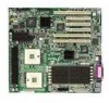
Server Board Connector and Component Locations,
 |
UPC - 735858152891
View all Intel SHG2 manuals
Add to My Manuals
Save this manual to your list of manuals |
Page 11 highlights
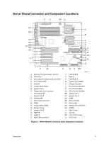
Server Board Connector and Component Locations II JJ KK LL HH A GG B FF EE DD CC BB AA Z Y C D E F H J G I K L M N O P Q X W V U T SR A Primary Processor Socket (CPU1) B CPU2 Fan C Secondary Processor Socket (CPU2) D Front Panel USB E Serial B F Jumper Block CN27 G System Fan 5 H Floppy disk drive connector I Secondary IDE J System Fan 6 K Primary IDE L Front Panel connector M IPMB N Jumper Block CN43 O System Fan 3 P System Fan 4 Q HSBP B R HSBP A S HDD LED Connector OM14357 T LVD SCSI B U Battery V LVD SCSI A W Jumper block CN53 X Chassis Intrusion Y PCI-X 64-bit/133 MHz Z PCI 32-bit/33 MHz AA PCI-X 64-bit/100 MHz BB System Fan 1 CC System Fan 2 DD ICMB EE NIC1 (10/100) FF NIC2 (Gbit) GG System I/O connectors HH DIMMs II Main Power JJ Aux Sig KK +12 V CPU Power LL CPU1 Fan Figure 2. Server Board Connector and Component Locations Description 11
-
 1
1 -
2
-
3
-
4
-
5
-
 6
6 -
 7
7 -
 8
8 -
 9
9 -
 10
10 -
 11
11 -
 12
12 -
 13
13 -
 14
14 -
 15
15 -
 16
16 -
17
-
18
-
19
-
20
-
21
-
22
-
23
-
24
-
25
-
26
-
27
-
28
-
29
-
30
-
31
-
32
-
33
-
34
-
35
-
36
-
37
-
38
-
39
-
40
-
41
-
42
-
43
-
44
-
45
-
46
-
47
-
48
-
49
-
50
-
51
-
52
-
53
-
54
-
55
-
56
-
57
-
58
-
59
-
60
-
61
-
62
-
63
-
64
-
65
-
66
-
67
-
68
-
69
-
70
-
71
-
72
-
73
-
74
-
75
-
76
-
77
-
78
-
79
-
80
-
81
-
82
-
83
-
84
-
85
-
86
-
87
-
88
-
89
-
90
-
91
-
92
-
93
-
94
-
95
-
96
-
97
-
98
-
99
-
100
 |
 |
