Intel SHG2 Product Guide - Page 90
Enabling PCI-X on Slot 6 and Disabling On-board SCSI - case
 |
UPC - 735858152891
View all Intel SHG2 manuals
Add to My Manuals
Save this manual to your list of manuals |
Page 90 highlights
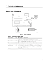
Table 8. Configuration Jumper (CN27) Jumper Name Pins What it does at system reset BIOS Write Protect 1-2 If these pins are jumpered, write protect is disabled allowing the BIOS boot block to be updated. This feature is used in the rare case that a BIOS update requires a BIOS boot block update as well. These pins should not be jumpered for normal operation. BMC Write Protect 3-4 If these pins are jumpered, write protect is disabled allowing the BMC boot block to be updated. This feature is used in the rare case that a BIOS update requires a BMC boot block update as well. These pins should not be jumpered for normal operation. Table 9. Configuration Jumper (CN53) Jumper Name Pins What it does at system reset PCIX1 DIS 1-2 Placing a jumper on pins 1-2 disables the 100 MHz PCI-X mode for the CIOBX2 primary channel and forces the bus to run 66 MHz PCI. The primary channel consists of Slot 1, Slot 2 and Gbit. In the default configuration, pins 1-2 are not jumpered therefore the primary channel is configured for 100 MHz PCI-X. PCIX2 DIS 3-4 Placing a jumper on pins 3-4 disables the PCI-X mode for the CIOBX2 secondary channel and forces the bus to run 66 MHz PCI. The secondary channel consists of Slot 6 and the on-board SCSI. In the default configuration, pins 3-4 are jumpered therefore the secondary channel is configured for 66 MHz PCI and on-board SCSI is enabled. Enabling PCI-X on Slot 6 and Disabling On-board SCSI ✏ NOTE Enabling the 133 MHz PCI-X on Slot 6 disables the on-board SCSI. To enable the 133 MHz PCI-X on Slot 6, follow these instructions: 1. Enter BIOS setup. 2. While in BIOS setup, remove the jumper from CN53 pins 3-4. 3. In BIOS setup disable the on-board SCSI. 4. Select Save & Exit BIOS setup. 5. While the system is posting, shutdown the system by pushing the front panel power button. 6. While the system in off, plug a PCI-X card into Slot 6. 7. Push the front panel power button to power up the system. 8. Slot 6 is now 133 MHz PCI-X capable. 90 Intel Server Board SHG2 Product Guide
-
 1
1 -
2
-
3
-
4
-
5
-
6
-
7
-
8
-
9
-
10
-
11
-
12
-
13
-
14
-
15
-
16
-
17
-
18
-
19
-
20
-
21
-
22
-
23
-
24
-
25
-
26
-
27
-
28
-
29
-
30
-
31
-
32
-
33
-
34
-
35
-
36
-
37
-
38
-
39
-
40
-
41
-
42
-
43
-
44
-
45
-
46
-
47
-
48
-
49
-
50
-
51
-
52
-
53
-
54
-
55
-
56
-
57
-
58
-
59
-
60
-
61
-
62
-
63
-
64
-
65
-
66
-
67
-
68
-
69
-
70
-
71
-
72
-
73
-
74
-
75
-
76
-
77
-
78
-
79
-
80
-
81
-
82
-
83
-
84
-
 85
85 -
 86
86 -
 87
87 -
 88
88 -
 89
89 -
 90
90 -
 91
91 -
 92
92 -
 93
93 -
 94
94 -
 95
95 -
96
-
97
-
98
-
99
-
100
 |
 |
