Intel SHG2 Product Guide - Page 51
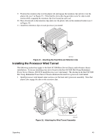
Attaching the Wind Tunnel Intake and Exhaust, Attach CPU Fan cables.
 |
UPC - 735858152891
View all Intel SHG2 manuals
Add to My Manuals
Save this manual to your list of manuals |
Page 51 highlights
3. Attach the air intake fan assembly to the side of the heat sink wind tunnel closest to the front of the chassis. a. Press both sides of the air intake section to bend tabs inward (see 1 in Figure 34). b. Insert tabs into slots on the wind tunnel center section (see 2 in Figure 34). c. Press the air intake section downward to engage the assembly (see 3 in Figure 34). 2 1 3 1 OM14371 Figure 34. Attaching the Wind Tunnel Intake and Exhaust 4. Attach the air exhaust fan assembly to the heat sink wind tunnel. a. Press both sides of the air exhaust section to bend tabs inward (see 1 in Figure 35). b. Insert tabs into slots on the wind tunnel center section (see 2 in Figure 35). c. Press the air intake section downward to engage the assembly (see 3 in Figure 35). 2 1 3 1 OM14374 Figure 35. Attaching the Wind Tunnel Intake and Exhaust 5. Attach CPU Fan cable(s). See "Making Connections to the Server Board" on page 35 for fan connector location information. Upgrading 51
-
 1
1 -
2
-
3
-
4
-
5
-
6
-
7
-
8
-
9
-
10
-
11
-
12
-
13
-
14
-
15
-
16
-
17
-
18
-
19
-
20
-
21
-
22
-
23
-
24
-
25
-
26
-
27
-
28
-
29
-
30
-
31
-
32
-
33
-
34
-
35
-
36
-
37
-
38
-
39
-
40
-
41
-
42
-
43
-
44
-
45
-
 46
46 -
 47
47 -
 48
48 -
 49
49 -
 50
50 -
 51
51 -
 52
52 -
 53
53 -
 54
54 -
 55
55 -
 56
56 -
57
-
58
-
59
-
60
-
61
-
62
-
63
-
64
-
65
-
66
-
67
-
68
-
69
-
70
-
71
-
72
-
73
-
74
-
75
-
76
-
77
-
78
-
79
-
80
-
81
-
82
-
83
-
84
-
85
-
86
-
87
-
88
-
89
-
90
-
91
-
92
-
93
-
94
-
95
-
96
-
97
-
98
-
99
-
100
 |
 |
