JVC DLA-RS45U 288 page operation manual for D-ILA Projectors DLA-RS65, DLA-RS5 - Page 15
Controls and features
 |
View all JVC DLA-RS45U manuals
Add to My Manuals
Save this manual to your list of manuals |
Page 15 highlights
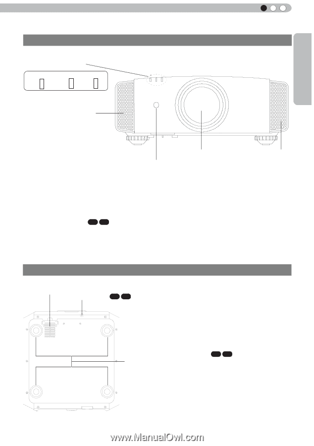
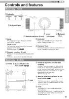
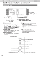
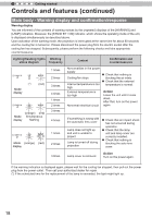
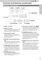
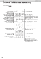
Getting Started Controls and features Main body - Front ③ Indicator STANDBY/ON LAMP WARNING ENGLISH ④ Exhaust Vent ① Lens ④ Exhaust ② Remote receiver (front) Lens cover Vent ① Lens This is a projection lens. Please do not look inside during projection. Lens cover The lens cover opens/closes when the power supply is turned on/off. (Reference page: 66) 65 55 ③ Indicator Please see "About the indicator display" for details. (Reference page: 17) ④ Exhaust Vent Warm air flows out in order to cool the interior of the set. Please do not block the vents. ② Remote receiver (front) Please aim the remote control at this area when using it. (*) There is also a remote receiver at the rear. Main body - Bottom ⑤ Inlets ⑥ Manual button for lens cover 65 55 ⑤ Inlets (at 3 points on the rear/ bottom) In order to cool the inside of the unit, air is let inside. Do not block or prevent the outflow of hot air. Doing so could lead to failure of the unit. (*) There are inlets at two points on the right and left sides of the rear side. (Reference page: 16) ⑦ Feet ⑥ Manual operation button of the lens cover 65 55 The lens cover can be opened when pressed down.It is used for maintenance and not used during normal use. ⑦ Feet The height (0 to 5 mm) can be adjusted by turning the foot. When the foot is removed, it can be used as the mounting holes for the ceiling mount bracket. (Reference page: 24) 15
-
 1
1 -
2
-
3
-
4
-
5
-
6
-
7
-
8
-
9
-
 10
10 -
 11
11 -
 12
12 -
 13
13 -
 14
14 -
 15
15 -
 16
16 -
 17
17 -
 18
18 -
 19
19 -
 20
20 -
21
-
22
-
23
-
24
-
25
-
26
-
27
-
28
-
29
-
30
-
31
-
32
-
33
-
34
-
35
-
36
-
37
-
38
-
39
-
40
-
41
-
42
-
43
-
44
-
45
-
46
-
47
-
48
-
49
-
50
-
51
-
52
-
53
-
54
-
55
-
56
-
57
-
58
-
59
-
60
-
61
-
62
-
63
-
64
-
65
-
66
-
67
-
68
-
69
-
70
-
71
-
72
-
73
-
74
-
75
-
76
-
77
-
78
-
79
-
80
-
81
-
82
-
83
-
84
-
85
-
86
-
87
-
88
-
89
-
90
-
91
-
92
-
93
-
94
-
95
-
96
-
97
-
98
-
99
-
100
-
101
-
102
-
103
-
104
-
105
-
106
-
107
-
108
-
109
-
110
-
111
-
112
-
113
-
114
-
115
-
116
-
117
-
118
-
119
-
120
-
121
-
122
-
123
-
124
-
125
-
126
-
127
-
128
-
129
-
130
-
131
-
132
-
133
-
134
-
135
-
136
-
137
-
138
-
139
-
140
-
141
-
142
-
143
-
144
-
145
-
146
-
147
-
148
-
149
-
150
-
151
-
152
-
153
-
154
-
155
-
156
-
157
-
158
-
159
-
160
-
161
-
162
-
163
-
164
-
165
-
166
-
167
-
168
-
169
-
170
-
171
-
172
-
173
-
174
-
175
-
176
-
177
-
178
-
179
-
180
-
181
-
182
-
183
-
184
-
185
-
186
-
187
-
188
-
189
-
190
-
191
-
192
-
193
-
194
-
195
-
196
-
197
-
198
-
199
-
200
-
201
-
202
-
203
-
204
-
205
-
206
-
207
-
208
-
209
-
210
-
211
-
212
-
213
-
214
-
215
-
216
-
217
-
218
-
219
-
220
-
221
-
222
-
223
-
224
-
225
-
226
-
227
-
228
-
229
-
230
-
231
-
232
-
233
-
234
-
235
-
236
-
237
-
238
-
239
-
240
-
241
-
242
-
243
-
244
-
245
-
246
-
247
-
248
-
249
-
250
-
251
-
252
-
253
-
254
-
255
-
256
-
257
-
258
-
259
-
260
-
261
-
262
-
263
-
264
-
265
-
266
-
267
-
268
-
269
-
270
-
271
-
272
-
273
-
274
-
275
-
276
-
277
-
278
-
279
-
280
-
281
-
282
-
283
-
284
-
285
-
286
-
287
-
288
 |
 |