Lantronix G520 G520 User Guide - Page 27
Back Panel, LEDs, Top Panel LEDs
 |
View all Lantronix G520 manuals
Add to My Manuals
Save this manual to your list of manuals |
Page 27 highlights
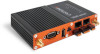
Back Panel Figure 2-2 G520 Series Back View 2: Introduction 1 23 4 ID Connection Name 1 Cellular diversity antenna (left) Cellular main antenna (right) 2 microSD card slot 3 Last Gasp switch (OFF by default) 4 GNSS antenna 5 SIM #1 / SIM # 2 Mini SIM slots 51 LEDs Top Panel LEDs Table 2-4 describes the top panel LEDs as shown from top to bottom in Figure 2-1. Name Alert Color Red User programmable #1 Blue User programmable #2 Blue Table 2-4 Top Panel LEDs Status OFF Description No alert, device is running smoothly Flashing Cellular module reboot, Linux kernel booting ON Hardware fault OFF User configurable via software Flashing User configurable via software ON User configurable via software OFF User configurable via software Flashing User configurable via software ON User configurable via software G520 Series IoT Cellular Gateway User Guide 27
-
 1
1 -
2
-
3
-
4
-
5
-
6
-
7
-
8
-
9
-
10
-
11
-
12
-
13
-
14
-
15
-
16
-
17
-
18
-
19
-
20
-
21
-
 22
22 -
 23
23 -
 24
24 -
 25
25 -
 26
26 -
 27
27 -
 28
28 -
 29
29 -
 30
30 -
 31
31 -
 32
32 -
33
-
34
-
35
-
36
-
37
-
38
-
39
-
40
-
41
-
42
-
43
-
44
-
45
-
46
-
47
-
48
-
49
-
50
-
51
-
52
-
53
-
54
-
55
-
56
-
57
-
58
-
59
-
60
-
61
-
62
-
63
-
64
-
65
-
66
-
67
-
68
-
69
-
70
-
71
-
72
-
73
-
74
-
75
-
76
-
77
-
78
-
79
-
80
-
81
-
82
-
83
-
84
-
85
-
86
-
87
-
88
-
89
-
90
-
91
-
92
-
93
-
94
-
95
-
96
-
97
-
98
-
99
-
100
-
101
-
102
-
103
-
104
-
105
-
106
-
107
-
108
-
109
-
110
-
111
-
112
-
113
-
114
-
115
-
116
-
117
-
118
-
119
-
120
-
121
-
122
-
123
-
124
-
125
-
126
-
127
-
128
-
129
-
130
-
131
-
132
-
133
-
134
-
135
-
136
-
137
-
138
-
139
-
140
-
141
-
142
-
143
-
144
-
145
-
146
-
147
-
148
-
149
-
150
-
151
-
152
-
153
-
154
-
155
-
156
-
157
-
158
-
159
-
160
-
161
-
162
-
163
-
164
-
165
-
166
-
167
-
168
-
169
-
170
-
171
-
172
-
173
-
174
-
175
-
176
-
177
-
178
-
179
-
180
-
181
-
182
-
183
-
184
-
185
-
186
-
187
-
188
-
189
-
190
-
191
-
192
-
193
-
194
-
195
-
196
-
197
-
198
-
199
-
200
-
201
-
202
-
203
-
204
-
205
-
206
-
207
-
208
-
209
-
210
-
211
-
212
-
213
-
214
-
215
-
216
-
217
-
218
-
219
-
220
-
221
-
222
-
223
-
224
-
225
 |
 |
