Lantronix G520 G520 User Guide - Page 76
LED Configuration, System > LED Configuration
 |
View all Lantronix G520 manuals
Add to My Manuals
Save this manual to your list of manuals |
Page 76 highlights
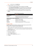
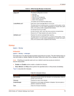
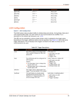
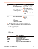
Shortcut @annually @monthly @weekly @daily @midnight @hourly Equivalent 0 0 1 1 * 0 0 1 * * 0 0 * * 0 0 0 * * * 0 0 * * * 0 * * * * Description Every year Every month Every week Every day Every day Every hour 8: System LED Configuration System > LED Configuration The G520 series router provides 9 LEDs to indicate status and activity. Among these, there are 2 user-programmable LEDs. The other LEDs are not recommended to be modified. For a description of the default LED behaviors, see LEDs. The LED can be controlled by various system events, which is selected by the trigger option. Depending on the trigger, additional options must be specified. See Table 8-10 which lists some trigger descriptions. The UI displays some triggers not listed in the table, but these are not recommended to be used. Trigger none timer defaulton heartbeat Table 8-10 Trigger Descriptions Description The LED is always in the default state. This is useful to declare an LED to be always ON. The LED blinks with the configured On/ Off frequency. Options: On-state delay: time in milliseconds that the LED is On. Off-state delay: time in milliseconds that the LED is Off. This trigger option is deprecated. Use trigger = none and default = On instead. The LED flashes to simulate actual heartbeat thump-thump-pause. The frequency is in direct proportion to 1minute average CPU load. Examples LED always on: LED name: any LED Default: On Trigger: none LED is 100ms On / 200ms Off: LED name: any LED Default: On Trigger: timer On-State Delay: 100 Off-State Delay: 200 LED blinks in heartbeat pattern: LED name: any LED Default: Off Trigger: heartbeat G520 Series IoT Cellular Gateway User Guide 76
-
 1
1 -
2
-
3
-
4
-
5
-
6
-
7
-
8
-
9
-
10
-
11
-
12
-
13
-
14
-
15
-
16
-
17
-
18
-
19
-
20
-
21
-
22
-
23
-
24
-
25
-
26
-
27
-
28
-
29
-
30
-
31
-
32
-
33
-
34
-
35
-
36
-
37
-
38
-
39
-
40
-
41
-
42
-
43
-
44
-
45
-
46
-
47
-
48
-
49
-
50
-
51
-
52
-
53
-
54
-
55
-
56
-
57
-
58
-
59
-
60
-
61
-
62
-
63
-
64
-
65
-
66
-
67
-
68
-
69
-
70
-
 71
71 -
 72
72 -
 73
73 -
 74
74 -
 75
75 -
 76
76 -
 77
77 -
 78
78 -
 79
79 -
 80
80 -
 81
81 -
82
-
83
-
84
-
85
-
86
-
87
-
88
-
89
-
90
-
91
-
92
-
93
-
94
-
95
-
96
-
97
-
98
-
99
-
100
-
101
-
102
-
103
-
104
-
105
-
106
-
107
-
108
-
109
-
110
-
111
-
112
-
113
-
114
-
115
-
116
-
117
-
118
-
119
-
120
-
121
-
122
-
123
-
124
-
125
-
126
-
127
-
128
-
129
-
130
-
131
-
132
-
133
-
134
-
135
-
136
-
137
-
138
-
139
-
140
-
141
-
142
-
143
-
144
-
145
-
146
-
147
-
148
-
149
-
150
-
151
-
152
-
153
-
154
-
155
-
156
-
157
-
158
-
159
-
160
-
161
-
162
-
163
-
164
-
165
-
166
-
167
-
168
-
169
-
170
-
171
-
172
-
173
-
174
-
175
-
176
-
177
-
178
-
179
-
180
-
181
-
182
-
183
-
184
-
185
-
186
-
187
-
188
-
189
-
190
-
191
-
192
-
193
-
194
-
195
-
196
-
197
-
198
-
199
-
200
-
201
-
202
-
203
-
204
-
205
-
206
-
207
-
208
-
209
-
210
-
211
-
212
-
213
-
214
-
215
-
216
-
217
-
218
-
219
-
220
-
221
-
222
-
223
-
224
-
225
 |
 |
