Marantz SR6004 SR6004 / SR5004 User Manual - English - Page 11
Rear Panel - setup
 |
View all Marantz SR6004 manuals
Add to My Manuals
Save this manual to your list of manuals |
Page 11 highlights
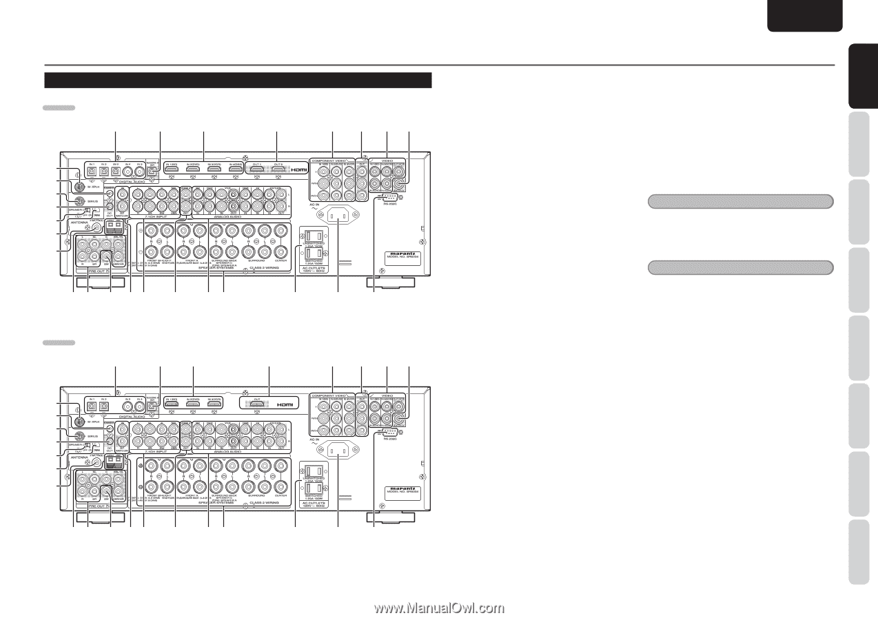
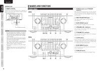
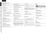
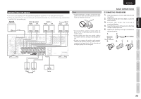
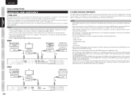
REAR PANEL SR6004 q w e @6 @5 @4 @3 @2 @1 @0 !9 !8 !7 !!6 5 !4 !3 !2 SR5004 @6 @5 @4 @3 @2 @1 @0 q we !9 !8 !7 !!6 5 !4 !3 !2 r t y ui !1 !0 o r t y ui !1 !0 o ENGLISH q DIGITAL AUDIO IN terminals (Optical and Coaxial) Connect these terminals to the digital signal output terminal(s) of the digital component (such as DVD player, CD player or DSS system). w DIGITAL AUDIO REC / ZONE B OUT terminal (Optical) Connect this terminal to the digital signal input terminal(s) of the digital recording component (such as a CD recorder) or another AV amplifier. (Page 21) e HDMI IN terminals Connect these terminals to a Blu-ray disc player or DVD player equipped with an HDMI output terminal(s). (Page 14) r HDMI OUT terminals Connect these terminals to a TV set or projector equipped with an HDMI input terminal(s). (Page 14) t COMPONENT VIDEO IN terminals Connect these terminals to a video component equipped with component video output terminal(s). (Page 13) y COMPONENT VIDEO OUT terminals Connect these terminals to a monitor TV or projector equipped with component video input terminal(s). (Page 13) u VIDEO IN / OUT terminals Connect these terminals to the video terminal(s) of a video component. (Page 13) i VIDEO MONITOR OUT terminal Connect this terminal to the video input terminal(s) of a monitor TV or projector. (Page 13) o RS-232C terminal The RS-232C port is to be used in conjunction with an external controller to control the operation of the unit by using an external device. !0 AC IN Plug the supplied power cable into this AC INLET and then into the power outlet on the wall. NAMES AND FUNCTION !1 AC OUTLETS Connect the AC power cables of components such as a DVD and CD player to these outlets. SWITCHED and UNSWITCHED outlets are provided. The one marked SWITCHED provides power only when the unit is turned on and is useful for components which you use every time you play your system. The one marked UNSWITCHED is always live as long as the unit is plugged into a live outlet. A component connected here may be left on permanently, or may be switched off with via its own power switch. Note When ZONE A or ZONE B is on, power will also be supplied to the AC outlets on the SWITCHED side in the same manner as the UNSWITCHED side, regardless of whether the unit is turned on or in standby mode. Caution • In order to avoid potential turn-off thumps, anything plugged into this outlet should be powered up before this unit is turned on. • The capacity of this AC outlet is 150W. Do not connect devices that consume electricity more than the capacity of this outlet. If the total power consumption of the connected devices exceeds the capacity, the protection circuit shuts down the power supply. !2 Speaker outputs terminals Connect the speakers to these terminals. (Page 11) !3 ANALOG AUDIO IN/OUT terminals Connect these terminals to the audio terminal(s) of an audio or video component. (Page 13) !4 ZONE A OUT terminals These are the audio output jacks for the ZONE A. Connect these jacks to optional audio power amplifiers to listen the source selected by the ZONE system in a remote room. (Page 21) !5 7.1 CH INPUT terminals By connecting a DVD Audio player, Super Audio CD multichannel player, or other components that has a multichannel port, you can playback the audio with 5.1 channel or 7.1 channel outputs. (Page 20) !6 REMOTE CONT. IN/OUT terminals Connect to a Marantz component equipped with remote control (RC-5) terminals. (Page 22) 9 OTHERS TROUBLESHOOTING ADVANCED OPERATION SETUP ADVANCED CONNECTIONS BASIC OPERATION BASIC NAMES AND CONNECTIONS FUNCTIONS
-
 1
1 -
2
-
3
-
4
-
5
-
 6
6 -
 7
7 -
 8
8 -
 9
9 -
 10
10 -
 11
11 -
 12
12 -
 13
13 -
 14
14 -
 15
15 -
 16
16 -
17
-
18
-
19
-
20
-
21
-
22
-
23
-
24
-
25
-
26
-
27
-
28
-
29
-
30
-
31
-
32
-
33
-
34
-
35
-
36
-
37
-
38
-
39
-
40
-
41
-
42
-
43
-
44
-
45
-
46
-
47
-
48
-
49
-
50
-
51
-
52
-
53
-
54
-
55
-
56
-
57
-
58
-
59
-
60
-
61
-
62
-
63
-
64
-
65
-
66
-
67
-
68
-
69
-
70
-
71
-
72
-
73
-
74
-
75
-
76
-
77
-
78
-
79
-
80
-
81
-
82
-
83
-
84
-
85
-
86
-
87
-
88
-
89
-
90
-
91
-
92
-
93
-
94
-
95
-
96
 |
 |