Marantz SR6004 SR6004 / SR5004 User Manual - English - Page 14
Connecting Audio Components
 |
View all Marantz SR6004 manuals
Add to My Manuals
Save this manual to your list of manuals |
Page 14 highlights
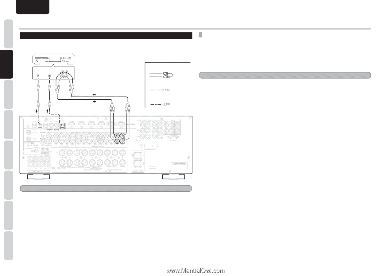
NAMES AND FUNCTIONS CONNECTIONS BASIC ENGLISH BASIC CONNECTIONS CONNECTING AUDIO COMPONENTS The output audio signal from the CD/CDR OUT jack is the same signal which is currently selected. CD recorder DIGITAL DIGITAL OUTPUT INPUT OUT IN L L R R LR RL IN 2 REC/ZONE B OUT RL LR ANALOG AUDIO CD/CDR L R IN OUT LR Analog Audio Digital Audio (coaxial) Digital Audio (optical) CONNECTING DIGITAL AUDIO COMPONENTS • Refer to the instructions for each component. To setup the digital audio format of CD player, or other digital source's connected to digital input jacks. • Use fiber optical cables (optical) for optical input jacks and REC/ZONE B optical output jack. Use 75 ohms coaxial cables (for digital audio or video) for coaxial input jacks. • You can designate the input for each digital input/output jacks according to your component. (See page 25) Notes • The digital signal jacks on this unit conform to the EIA standard. If you use a cable that does not conform to this standard, this unit may not function properly. • Each type of audio jack works independently. Signals input through the digital and analog jacks are output through the corresponding digital and analog jacks, respectively. BASIC OPERATION ADVANCED CONNECTIONS SETUP ADVANCED OPERATION TROUBLESHOOTING Notes • Do not connect this unit and other components to mains power until all connections between components have been completed. • Insert all plugs and connectors securely. Incomplete connections may make noise. • Be sure to connect the left and right channels properly. Red connectors are for the R (right) channel, and white connectors are for the L (left) channel. • Be sure to connect input and output properly. • Refer to the instructions for each component that is connected to this unit. • Do not bind audio/video connection cables with power cables and speaker cables this will result in generating a hum or other noise. 12 OTHERS
-
 1
1 -
2
-
3
-
4
-
5
-
6
-
7
-
8
-
 9
9 -
 10
10 -
 11
11 -
 12
12 -
 13
13 -
 14
14 -
 15
15 -
 16
16 -
 17
17 -
 18
18 -
 19
19 -
20
-
21
-
22
-
23
-
24
-
25
-
26
-
27
-
28
-
29
-
30
-
31
-
32
-
33
-
34
-
35
-
36
-
37
-
38
-
39
-
40
-
41
-
42
-
43
-
44
-
45
-
46
-
47
-
48
-
49
-
50
-
51
-
52
-
53
-
54
-
55
-
56
-
57
-
58
-
59
-
60
-
61
-
62
-
63
-
64
-
65
-
66
-
67
-
68
-
69
-
70
-
71
-
72
-
73
-
74
-
75
-
76
-
77
-
78
-
79
-
80
-
81
-
82
-
83
-
84
-
85
-
86
-
87
-
88
-
89
-
90
-
91
-
92
-
93
-
94
-
95
-
96
 |
 |