Nintendo DMG-01 Manual - Page 14
Writing a value XBB - X = Don't care, B
 |
View all Nintendo DMG-01 manuals
Add to My Manuals
Save this manual to your list of manuals |
Page 14 highlights
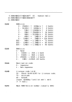
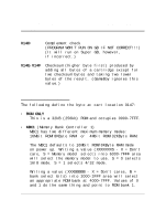
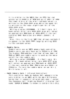
2.6. Cartridge Types Game BoyTM CPU Manual Rom bank 0 is not accessible from 4000-7FFF and can only be read from 0000-3FFF. If memory model is set to 4/32: Writing a value (XXXXXXBB - X = Don't care, B = bank select bits) into 4000-5FFF area will select an appropriate RAM bank at A000-C000. Before you can read or write to a RAM bank you have to enable it by writing a XXXX1010 into 0000-1FFF area*. To disable RAM bank operations write any value but XXXX1010 into 0000-1FFF area. Disabling a RAM bank probably protects that bank from false writes during power down of the GameBoy. (NOTE: Nintendo suggests values $0A to enable and $00 to disable RAM bank!!) If memory model is set to 16/8 mode: Writing a value (XXXXXXBB - X = Don't care, B = bank select bits) into 4000-5FFF area will set the two most significant ROM address lines. * NOTE: The Super Smart Card doesn't require this operation because it's RAM bank is ALWAYS enabled. Include this operation anyway to allow your code to work with both. • MBC2 (Memory Bank Controller 2): This memory controller works much like the MBC1 controller with the following exceptions: MBC2 will work with ROM sizes up to 2Mbit. Writing a value (XXXXBBBB - X = Don't cares, B = bank select bits) into 2000-3FFF area will select an appropriate ROM bank at 4000-7FFF. RAM switching is not provided. Unlike the MBC1 which uses external RAM, MBC2 has 512 x 4 bits of Page 14 V 1.01
-
 1
1 -
2
-
3
-
4
-
5
-
6
-
7
-
8
-
 9
9 -
 10
10 -
 11
11 -
 12
12 -
 13
13 -
 14
14 -
 15
15 -
 16
16 -
 17
17 -
 18
18 -
 19
19 -
20
-
21
-
22
-
23
-
24
-
25
-
26
-
27
-
28
-
29
-
30
-
31
-
32
-
33
-
34
-
35
-
36
-
37
-
38
-
39
-
40
-
41
-
42
-
43
-
44
-
45
-
46
-
47
-
48
-
49
-
50
-
51
-
52
-
53
-
54
-
55
-
56
-
57
-
58
-
59
-
60
-
61
-
62
-
63
-
64
-
65
-
66
-
67
-
68
-
69
-
70
-
71
-
72
-
73
-
74
-
75
-
76
-
77
-
78
-
79
-
80
-
81
-
82
-
83
-
84
-
85
-
86
-
87
-
88
-
89
-
90
-
91
-
92
-
93
-
94
-
95
-
96
-
97
-
98
-
99
-
100
-
101
-
102
-
103
-
104
-
105
-
106
-
107
-
108
-
109
-
110
-
111
-
112
-
113
-
114
-
115
-
116
-
117
-
118
-
119
-
120
-
121
-
122
-
123
-
124
-
125
-
126
-
127
-
128
-
129
-
130
-
131
-
132
-
133
-
134
-
135
-
136
-
137
-
138
-
139
 |
 |