Nintendo DMG-01 Manual - Page 40
FF10 NR 10
 |
View all Nintendo DMG-01 manuals
Add to My Manuals
Save this manual to your list of manuals |
Page 40 highlights
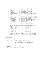
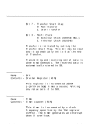
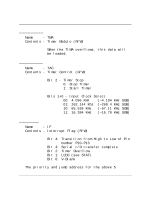
2.13.1. I/O Registers Game BoyTM CPU Manual interrupts are: Interrupt V-Blank LCDC Status Priority 1 2 Timer Overflow 3 Serial Transfer 4 Hi-Lo of P10-P13 5 Start Address $0040 $0048 - Modes 0, 1, 2 LYC=LY coincide (selectable) $0050 $0058 - when transfer is complete $0060 * When more than 1 interrupts occur at the same time only the interrupt with the highest priority can be acknowledged. When an interrupt is used a '0' should be stored in the IF register before the IE register is set. 9. FF10 (NR 10) Name - NR 10 Contents - Sound Mode 1 register, Sweep register (R/W) Bit 6-4 - Sweep Time Bit 3 - Sweep Increase/Decrease 0: Addition (frequency increases) 1: Subtraction (frequency decreases) Bit 2-0 - Number of sweep shift (n: 0-7) Sweep Time: 000: sweep off - no freq change 001: 7.8 ms (1/128Hz) 010: 15.6 ms (2/128Hz) 011: 23.4 ms (3/128Hz) Page 40 V 1.01
-
 1
1 -
2
-
3
-
4
-
5
-
6
-
7
-
8
-
9
-
10
-
11
-
12
-
13
-
14
-
15
-
16
-
17
-
18
-
19
-
20
-
21
-
22
-
23
-
24
-
25
-
26
-
27
-
28
-
29
-
30
-
31
-
32
-
33
-
34
-
 35
35 -
 36
36 -
 37
37 -
 38
38 -
 39
39 -
 40
40 -
 41
41 -
 42
42 -
 43
43 -
 44
44 -
 45
45 -
46
-
47
-
48
-
49
-
50
-
51
-
52
-
53
-
54
-
55
-
56
-
57
-
58
-
59
-
60
-
61
-
62
-
63
-
64
-
65
-
66
-
67
-
68
-
69
-
70
-
71
-
72
-
73
-
74
-
75
-
76
-
77
-
78
-
79
-
80
-
81
-
82
-
83
-
84
-
85
-
86
-
87
-
88
-
89
-
90
-
91
-
92
-
93
-
94
-
95
-
96
-
97
-
98
-
99
-
100
-
101
-
102
-
103
-
104
-
105
-
106
-
107
-
108
-
109
-
110
-
111
-
112
-
113
-
114
-
115
-
116
-
117
-
118
-
119
-
120
-
121
-
122
-
123
-
124
-
125
-
126
-
127
-
128
-
129
-
130
-
131
-
132
-
133
-
134
-
135
-
136
-
137
-
138
-
139
 |
 |
