Onkyo TX SR805 Owner Manual - Page 13
Front L/r, Center, Surr L/r, And Surr, Woofer, And Surr Back L/r - av receiver
 |
UPC - 751398007606
View all Onkyo TX SR805 manuals
Add to My Manuals
Save this manual to your list of manuals |
Page 13 highlights
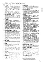
Getting to Know the AV Receiver-Continued M IR IN/OUT A commercially available IR receiver can be connected to the IR IN jack, allowing you to control the AV receiver while you're in Zone 2, or control it when it's out of sight, for example, installed in a cabinet. A commercially available IR emitter can be connected to the IR OUT jack to pass IR (infrared) remote control signals through to other components. N 12V TRIGGER OUT ZONE 2 This output can be connected to the 12-volt trigger input on a component in Zone 2. When Zone 2 is turned on on the AV receiver, a 12-volt trigger signal is output. O AC INLET The supplied power cord is connected here. The other end of the power cord should be connected to a suitable wall outlet. P DIGITAL COAXIAL IN 1, 2, and 3 These coaxial digital audio inputs are for connecting components with a coaxial digital audio output, such as a CD player or DVD player. They're assignable, which means you can assign each one to an input selector to suit your setup. See "Digital Input Setup" on page 52. Q DIGITAL OPTICAL IN 1, 2, and OUT These optical digital audio inputs are for connecting components with an optical digital audio output, such as a CD player or DVD player. They're assignable, which means you can assign each one to an input selector to suit your setup. See "Digital Input Setup" on page 52. The optical digital audio output is for connecting a digital recorder with an optical digital input, such as a CD recorder. R GND screw This screw is for connecting a turntable's ground wire. S CD IN This analog audio input is for connecting a CD player's analog audio output. T TAPE IN/OUT These analog audio input and output jacks are for connecting a recorder with an analog audio input and output, such as a cassette deck, MD recorder, etc. U AUX 1 IN A VCR for playback only or other video source can be connected here. There's S-Video and composite video input jacks for connecting the video signal. V GAME/TV IN A game console or TV output can be connected here. There's S-Video and composite video input jacks for connecting the video signal. W CBL/SAT IN A cable or satellite receiver can be connected here. There's S-Video and composite video input jacks for connecting the video signal. X VCR/DVR IN/OUT A video component, such as a VCR or DVR, can be connected here for recording and playback. There's S-Video and composite video input and output jacks for connecting the video signal. Y DVD IN This input is for connecting a DVD player. There's S-Video and composite video input jacks for connecting the video signal. Z FRONT L/R, CENTER, SURR L/R, and SURR BACK L/R SPEAKERS These terminal posts are for connecting the front L/R, center, surround L/R, and surround back L/R speakers. The FRONT L/R and SURR BACK L/R terminal posts can be used with front speakers and surround back speakers respectively, or used to bi-amp or bridge the front speakers. See "Bi-amping the Front Speakers" and "Bridging the Front Speakers (TX-SR875 only)" on page 24. The TX-SR805 does not support bridging. a MULTI CH input: FRONT L/R, CENTER, SUB- WOOFER, SURR L/R, and SURR BACK L/R This analog multichannel input is for connecting a component with a 5.1/7.1-channel analog audio output, such as a DVD player, DVD-Audio or SACD-capable player, or an MPEG decoder. b PRE OUT: FRONT L/R, CENTER, SUBWOOFER, SURR L/R, and SURR BACK L/R This 5.1/7.1 multichannel analog audio output can be connected to the analog audio input on a multichannel power amplifier for when you want to use the AV receiver solely as a preamplifier. The SUBWOOFER jack is for connecting a powered subwoofer. c PRE OUT: ZONE 2, ZONE 3 These analog audio outputs can be connected to the line inputs on amplifiers in Zone 2 and Zone 3. d ZONE 2 L/R SPEAKERS These terminal posts are for connecting speakers in Zone 2. e AC OUTLET (North American and European models only) These switched AC outlets can be used to supply power to other AV components. The type and number of outlets depends on the country in which you purchased your AV receiver. See pages 20-43 for hookup information. 13
-
 1
1 -
2
-
3
-
4
-
5
-
6
-
7
-
 8
8 -
 9
9 -
 10
10 -
 11
11 -
 12
12 -
 13
13 -
 14
14 -
 15
15 -
 16
16 -
 17
17 -
 18
18 -
19
-
20
-
21
-
22
-
23
-
24
-
25
-
26
-
27
-
28
-
29
-
30
-
31
-
32
-
33
-
34
-
35
-
36
-
37
-
38
-
39
-
40
-
41
-
42
-
43
-
44
-
45
-
46
-
47
-
48
-
49
-
50
-
51
-
52
-
53
-
54
-
55
-
56
-
57
-
58
-
59
-
60
-
61
-
62
-
63
-
64
-
65
-
66
-
67
-
68
-
69
-
70
-
71
-
72
-
73
-
74
-
75
-
76
-
77
-
78
-
79
-
80
-
81
-
82
-
83
-
84
-
85
-
86
-
87
-
88
-
89
-
90
-
91
-
92
-
93
-
94
-
95
-
96
-
97
-
98
-
99
-
100
-
101
-
102
-
103
-
104
-
105
-
106
-
107
-
108
-
109
-
110
-
111
-
112
-
113
-
114
-
115
-
116
-
117
-
118
-
119
-
120
 |
 |
