Onkyo TX SR805 Owner Manual - Page 38
Connecting a Game Console
 |
UPC - 751398007606
View all Onkyo TX SR805 manuals
Add to My Manuals
Save this manual to your list of manuals |
Page 38 highlights
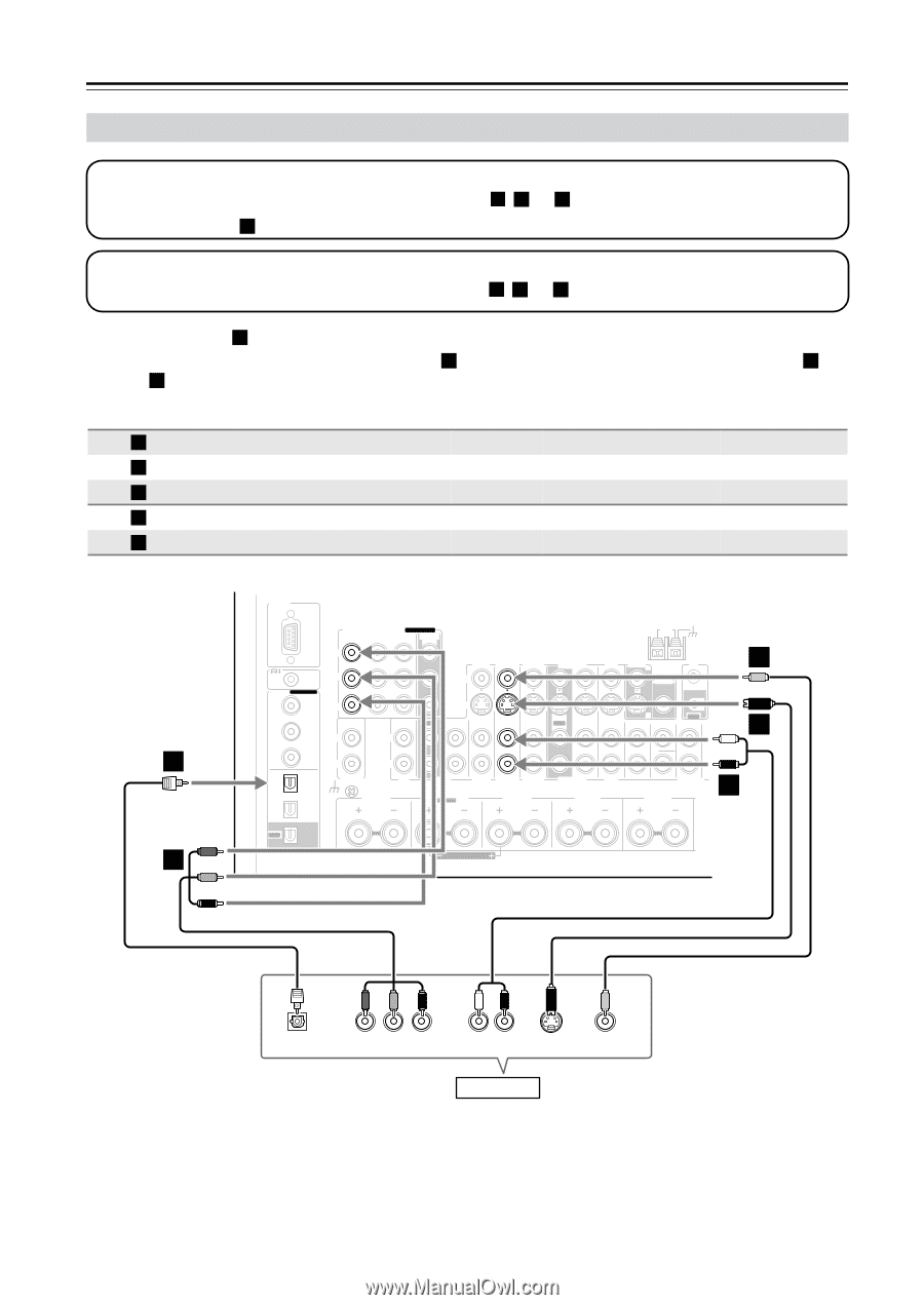
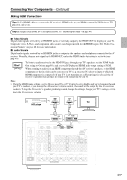
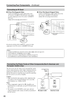
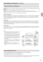
Connecting Your Components-Continued Connecting a Game Console Step 1: Video Connection Choose a video connection that matches your game console ( A , B , or C ), and then make the connection. If you use connection A , you must connect the AV receiver to your TV with the same type of connection. Step 2: Audio Connection Choose an audio connection that matches your DVD player ( a , b , or c ), and then make the connection. • With connection a , you can listen to and record audio from your game console or listen in Zone 2 or Zone 3. • To enjoy Dolby Digital and DTS, use connection b . (To record or listen in Zone 2 or Zone 3 as well, use a and b .) Connection A B C a b AV receiver COMPONENT VIDEO IN 3 GAME/TV IN S GAME/TV IN V GAME/TV IN L/R DIGITAL OPTICAL IN 1 Signal flow Game console Component video output S-Video output Composite video output Analog audio L/R output Digital coaxial output Picture quality Best Better Standard b A RS232 COMPONENT VIDEO ASSIGNABLE IN 3 IN 2 IN 1(DVD) MONITOR OUT Y REMOTE CB/PB CONTROL DIGITAL ASSIGNABLE COAXIAL IN 1 (DVD) CR/PR IN 2 (VCR/DVR) IN L IN OUT L AUX 1 GAME/TV CBL/SAT V VCR/DVR S IN IN IN IN OUT IN ANTENNA AM DVD MONITOR OUT V ZONE 2 OUT IR IN S OUT IN FRONT CENTER SURR IN 3 (CBL/SAT) R R OPTICAL PHONO IN 1 CD TAPE AUX 1 GAME/TV CBL/SAT VCR/DVR DVD (GAME/TV) GND ZONE2 R SURR BACK R Bi-AMP FRONT R SURR R IN 2 (CD) OUT SUBWOOFER MULTI CH a CENTER FRONT R (BTL) C B 38 OPTICAL OUT Y PB PR COMPONENT VIDEO OUT L R AUDIO OUT S VIDEO OUT VIDEO OUT Game Console
-
 1
1 -
2
-
3
-
4
-
5
-
6
-
7
-
8
-
9
-
10
-
11
-
12
-
13
-
14
-
15
-
16
-
17
-
18
-
19
-
20
-
21
-
22
-
23
-
24
-
25
-
26
-
27
-
28
-
29
-
30
-
31
-
32
-
 33
33 -
 34
34 -
 35
35 -
 36
36 -
 37
37 -
 38
38 -
 39
39 -
 40
40 -
 41
41 -
 42
42 -
 43
43 -
44
-
45
-
46
-
47
-
48
-
49
-
50
-
51
-
52
-
53
-
54
-
55
-
56
-
57
-
58
-
59
-
60
-
61
-
62
-
63
-
64
-
65
-
66
-
67
-
68
-
69
-
70
-
71
-
72
-
73
-
74
-
75
-
76
-
77
-
78
-
79
-
80
-
81
-
82
-
83
-
84
-
85
-
86
-
87
-
88
-
89
-
90
-
91
-
92
-
93
-
94
-
95
-
96
-
97
-
98
-
99
-
100
-
101
-
102
-
103
-
104
-
105
-
106
-
107
-
108
-
109
-
110
-
111
-
112
-
113
-
114
-
115
-
116
-
117
-
118
-
119
-
120
 |
 |