Onkyo TX SR805 Owner Manual - Page 50
Component Video Input Setup
 |
UPC - 751398007606
View all Onkyo TX SR805 manuals
Add to My Manuals
Save this manual to your list of manuals |
Page 50 highlights
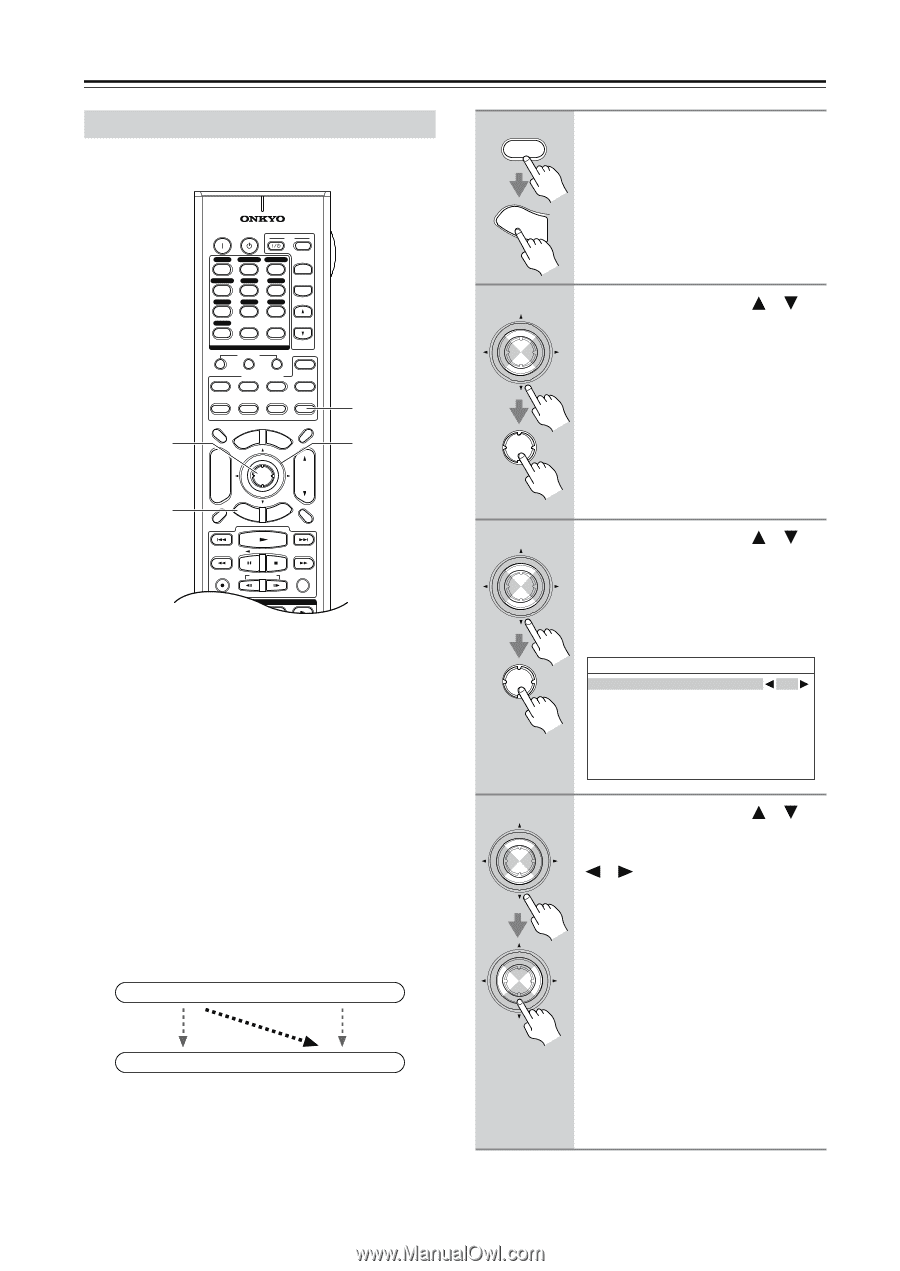
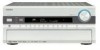
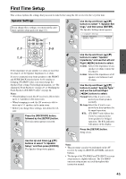
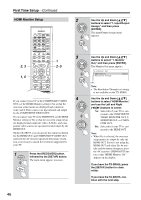
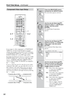
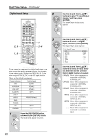
First Time Setup-Continued Component Video Input Setup 2, 3 1, 5 ON STANDBY TV INPUT DVD 1 VCR/DVR CBL/SAT 2 3 GAME/TV AUX1 AUX2 4 5 6 + TV CH - TAPE TUNER CD 7 8 9 PHONO D. TUN TV VOL +10 0 CLEAR --/--- 10 11 12 INPUT SELECTOR MACRO 1 2 3 ZONE3 DVD REMOTE MODE VCR CD CDR/MD ZONE2 TV DIMMER + CH DISC ALBUM - PREV CH DISPLAY CABLE SAT TOP MENU DOCK MENU RECEIVER TAPE/AMP SLEEP ENTER VOL GUIDE SETUP EXIT RETURN MUTING 1 2-4 REC PLAYLIST RANDOM STEREO LISTENING MODE SURR REPEAT AUDIO SUBTITLE PLAY MODE If you connect a video component to a COMPONENT VIDEO IN, you must assign that input to an input selector. For example, if you connect your DVD player to COMPONENT VIDEO IN 3, you must assign COM- PONENT VIDEO IN 3 to the DVD input selector. By default, the DVD input selector is assigned to COMPONENT VIDEO IN 1, and all of the other input selectors (i.e., VCR/DVR, CBL/SAT, GAME/TV, AUX 1, AUX 2, TAPE, TUNER, CD, PHONO) are assigned to the "- - -" option. If you've connected your TV to the AV receiver with a component video cable, you can set the AV receiver so that composite video and S-Video sources are upcon- verted (*) and output by the COMPONENT VIDEO OUT. You can set this for each input selector by selecting the "- - -" option. Composite video, S-Video Component video IN (*) OUT Composite video, S-Video Component video 1 RECEIVER Press the [RECEIVER] button, followed by the [SETUP] button. The main menu appears onscreen. SETUP 2 ENTER ENTER Use the Up and Down [ ]/[ ] buttons to select "1. Input/Output Assign," and then press [ENTER]. The Input/Output Assign menu appears. 3 ENTER ENTER Use the Up and Down [ ]/[ ] buttons to select "3. Component Video Input," and then press [ENTER]. The Component Video Input menu appears. 1-3.Component Video Input DVD IN1 VCR/DVR --- CBL/SAT --- GAME/TV --- AUX1 --- AUX2 --- 4 ENTER ENTER Use the Up and Down [ ]/[ ] buttons to select an input selector, and use the Left and Right [ ]/[ ] buttons to select: IN1: Select if the video component is connected to COMPONENT VIDEO IN 1. IN2: Select if the video component is connected to COMPONENT VIDEO IN 2. IN3: Select if the video component is connected to COMPONENT VIDEO IN 3. - - -: Select to output composite video and S-Video sources from the COMPONENT VIDEO OUT. 50
-
 1
1 -
2
-
3
-
4
-
5
-
6
-
7
-
8
-
9
-
10
-
11
-
12
-
13
-
14
-
15
-
16
-
17
-
18
-
19
-
20
-
21
-
22
-
23
-
24
-
25
-
26
-
27
-
28
-
29
-
30
-
31
-
32
-
33
-
34
-
35
-
36
-
37
-
38
-
39
-
40
-
41
-
42
-
43
-
44
-
 45
45 -
 46
46 -
 47
47 -
 48
48 -
 49
49 -
 50
50 -
 51
51 -
 52
52 -
 53
53 -
 54
54 -
 55
55 -
56
-
57
-
58
-
59
-
60
-
61
-
62
-
63
-
64
-
65
-
66
-
67
-
68
-
69
-
70
-
71
-
72
-
73
-
74
-
75
-
76
-
77
-
78
-
79
-
80
-
81
-
82
-
83
-
84
-
85
-
86
-
87
-
88
-
89
-
90
-
91
-
92
-
93
-
94
-
95
-
96
-
97
-
98
-
99
-
100
-
101
-
102
-
103
-
104
-
105
-
106
-
107
-
108
-
109
-
110
-
111
-
112
-
113
-
114
-
115
-
116
-
117
-
118
-
119
-
120
 |
 |