Onkyo TX SR805 Owner Manual - Page 23
Bi-amping the Front Speakers, Bi-amping Speaker Hookup - subwoofer
 |
UPC - 751398007606
View all Onkyo TX SR805 manuals
Add to My Manuals
Save this manual to your list of manuals |
Page 23 highlights
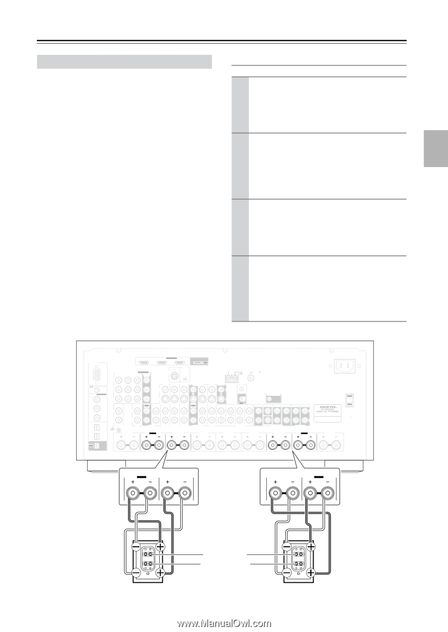
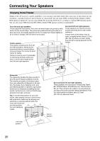
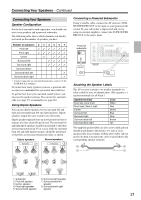
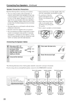
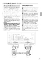
Connecting Your Speakers-Continued Bi-amping the Front Speakers The FRONT L/R and SURR BACK L/R terminal posts can be used with front speakers and surround back speakers respectively, or bi-amped to provide separate tweeter and woofer feeds for a pair of front speakers that support bi-amping, providing improved bass and treble performance. • When bi-amping is used, the AV receiver is able to drive up to 5.1 speakers in the main room. • For bi-amping, the FRONT L/R terminal posts connect to the front speakers' tweeter terminals. And the SURR BACK L/R terminal posts connect to the front speakers' woofer terminals. • Once you've completed the bi-amping connections shown below and turned on the AV receiver, you must set the Speaker Type setting to Bi-Amp to enable biamping (see page 45). Important: • When making the bi-amping connections, be sure to remove the jumper bars that link the speakers' tweeter (high) and woofer (low) terminals. • Bi-amping can only be used with speakers that support bi-amping. Refer to your speaker manual. • Use only front speakers with an impedance of 8 ohms or higher for bi-amping. Failure to do so may seriously damage the AV receiver. Bi-amping Speaker Hookup 1 Connect the AV receiver's FRONT R positive (+) terminal to the right speaker's positive (+) tweeter (high) terminal. And connect the AV receiver's FRONT R negative (-) terminal to the right speaker's negative (-) tweeter (high) terminal. 2 Connect the AV receiver's SURR BACK R positive (+) terminal to the right speaker's positive (+) woofer (low) terminal. And connect the AV receiver's SURR BACK R negative (-) terminal to the right speaker's negative (-) woofer (low) terminal. 3 Connect the AV receiver's FRONT L positive (+) terminal to the left speaker's positive (+) tweeter (high) terminal. And connect the AV receiver's FRONT L negative (-) terminal to the left speaker's negative (-) tweeter (high) terminal. 4 Connect the AV receiver's SURR BACK L positive (+) terminal to the left speaker's positive (+) woofer (low) terminal. And connect the AV receiver's SURR BACK L negative (-) terminal to the left speaker's negative (-) woofer (low) terminal. RS232 IN 3 COMPONENT VIDEO ASSIGNABLE IN 3 IN 2 IN 1(DVD) MONITOR OUT Y REMOTE CB/PB CONTROL DIGITAL ASSIGNABLE COAXIAL IN 1 (DVD) CR/PR HDMI ASSIGNABLE IN 2 IN 1 OUT XM SIRIUS AUX 1 GAME/TV CBL/SAT V VCR/DVR DVD S IN 2 (VCR/DVR) IN L IN OUT IN IN IN IN OUT IN IN L ANTENNA AM FM75 MONITOR OUT V IR IN 12V TRIGGER OUT ZONE 2 S OUT FRONT CENTER SURR SURR BACK FRONT CENTER SURR SURR BACK ZONE 2 ZONE 3 L IN 3 (CBL/SAT) R R OPTICAL PHONO IN 1 CD TAPE AUX 1 GAME/TV CBL/SAT VCR/DVR DVD (GAME/TV) GND ZONE2 R SURR BACK R Bi-AMP FRONT R SURR R IN 2 (CD) OUT SUBWOOFER MULTI CH CENTER SURR L SUBWOOFER PRE OUT FRONT L R PRE OUT SURR BACK L Bi-AMP AC INLET AC OUTLET AC 120V 60Hz SWITCHED 120W 1A MAX. ZONE2 L SURR BACK R Bi-AMP FRONT R FRONT L SURR BACK L Bi-AMP Woofer (low) Tweeter (high) Right speaker Left speaker 23
-
 1
1 -
2
-
3
-
4
-
5
-
6
-
7
-
8
-
9
-
10
-
11
-
12
-
13
-
14
-
15
-
16
-
17
-
 18
18 -
 19
19 -
 20
20 -
 21
21 -
 22
22 -
 23
23 -
 24
24 -
 25
25 -
 26
26 -
 27
27 -
 28
28 -
29
-
30
-
31
-
32
-
33
-
34
-
35
-
36
-
37
-
38
-
39
-
40
-
41
-
42
-
43
-
44
-
45
-
46
-
47
-
48
-
49
-
50
-
51
-
52
-
53
-
54
-
55
-
56
-
57
-
58
-
59
-
60
-
61
-
62
-
63
-
64
-
65
-
66
-
67
-
68
-
69
-
70
-
71
-
72
-
73
-
74
-
75
-
76
-
77
-
78
-
79
-
80
-
81
-
82
-
83
-
84
-
85
-
86
-
87
-
88
-
89
-
90
-
91
-
92
-
93
-
94
-
95
-
96
-
97
-
98
-
99
-
100
-
101
-
102
-
103
-
104
-
105
-
106
-
107
-
108
-
109
-
110
-
111
-
112
-
113
-
114
-
115
-
116
-
117
-
118
-
119
-
120
 |
 |