Onkyo TX SR805 Owner Manual - Page 22
Speaker Connection Precautions, Connecting the Speaker Cables, speaker cables, - power supply
 |
UPC - 751398007606
View all Onkyo TX SR805 manuals
Add to My Manuals
Save this manual to your list of manuals |
Page 22 highlights
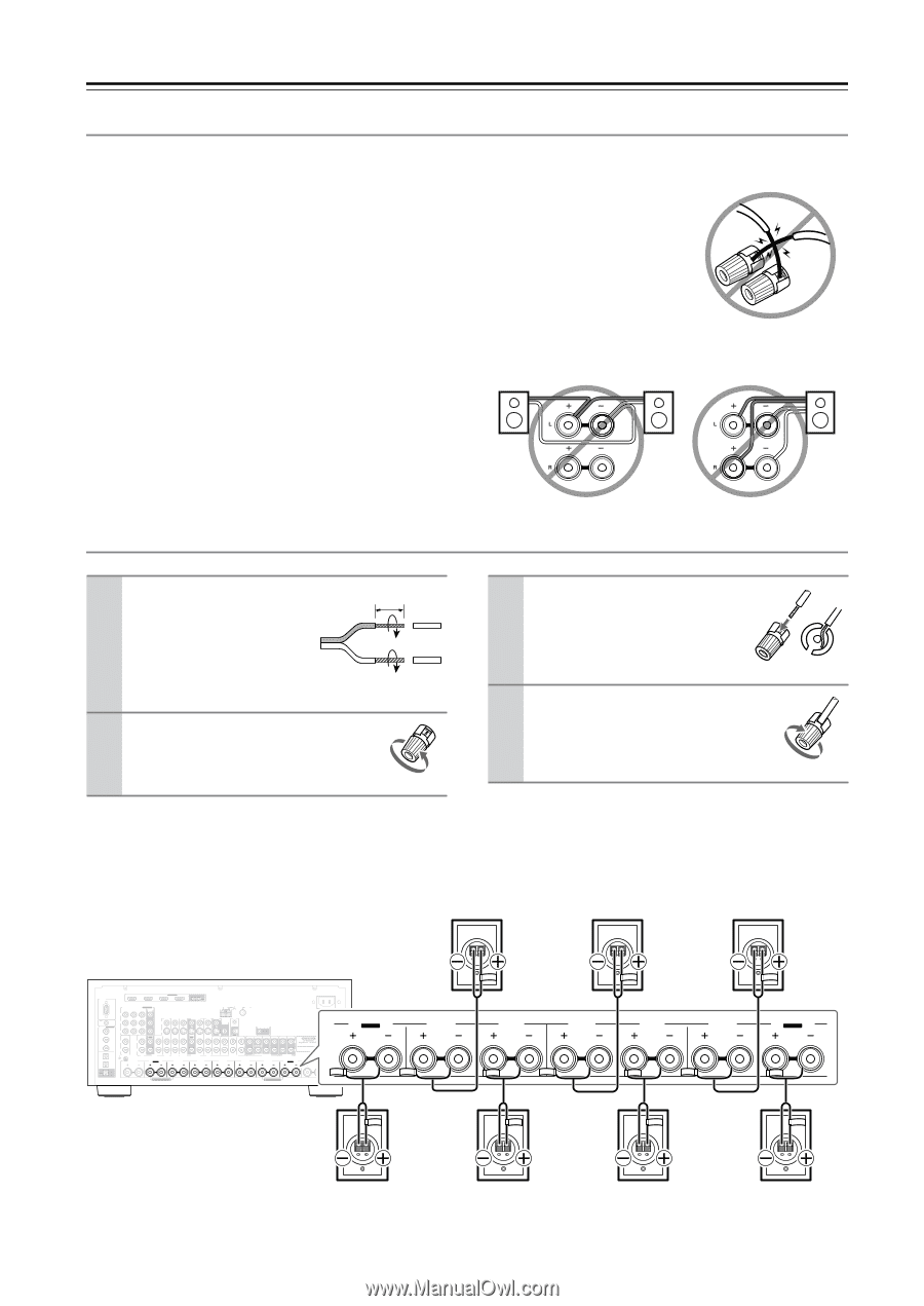
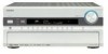
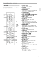
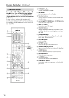
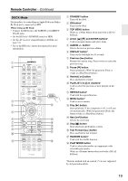
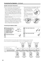
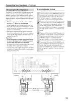
Connecting Your Speakers-Continued Speaker Connection Precautions Read the following before connecting your speakers: • You can connect speakers with an impedance of between 4 and 16 ohms. If the impedance of any of the connected speakers is 4 ohms or more but less than 6, be sure to set the speaker impedance to 4 ohms (see page 45). If you use speakers with a lower impedance, and use the amplifier at high volume levels for a long period of time, the built-in amp protection circuit may be activated. • Disconnect the power cord from the wall outlet before making any connections. • Read the instructions supplied with your speakers. • Pay close attention to speaker wiring polarity. Connect positive (+) terminals to only positive (+) terminals, and negative (-) terminals to only negative (-) terminals. If you get them the wrong way around, the sound will be out of phase and will sound unnatural. • Unnecessarily long or very thin speaker cables may affect the sound quality and should be avoided. • Be careful not to short the positive and negative wires. Doing so may damage the AV receiver. • Don't connect more than one cable to each speaker terminal. Doing so may damage the AV receiver. • Don't connect a speaker to several terminals. Connecting the Speaker Cables 1 Strip about 5/8" (15 mm) of insulation from the ends of the speaker cables, and twist the bare wires tightly, as shown. 2 Unscrew the terminal. 5/8" (15 mm) 3 Fully insert the bare wire. 4 Screw the terminal tight. The following illustration shows which speaker should be connected to each pair of terminals. If you're using only one surround back speaker, connect it to the SURR BACK L terminals. Front right speaker Center speaker Front left speaker RS232 HDMI ASSIGNABLE IN 4 IN 3 IN 2 IN 1 OUT COMPONENT VIDEO ASSIGNABLE IN 3 IN 2 IN 1(DVD) MONITOR OUT Y REMOTE CB/PB CONTROL DIGITAL ASSIGNABLE COAXIAL IN 1 (DVD) CR/PR IN 2 (VCR/DVR) IN L IN OUT L AUX 1 GAME/TV CBL/SAT V VCR/DVR S IN IN IN IN OUT IN ANTENNA AM FM75 DVD MONITOR OUT V ZONE 2 OUT IR IN 12V TRIGGER OUT ZONE 2 S OUT IN FRONT CENTER SURR SURR BACK FRONT CENTER SURR SURR BACK ZONE 2 ZONE 3 L IN 3 (CBL/SAT) R R OPTICAL PHONO IN 1 CD TAPE AUX 1 GAME/TV CBL/SAT VCR/DVR DVD (GAME/TV) GND ZONE2 R SURR BACK R Bi-AMP FRONT R SURR R IN 2 (CD) OUT SUBWOOFER MULTI CH CENTER SURR L SUBWOOFER PRE OUT FRONT L R PRE OUT SURR BACK L Bi-AMP FRONT R (BTL) FRONT L (BTL) AC INLET AC OUTLET AC 220-240V 50/60Hz SWITCHED 100W 0.45-0.41A MAX. ZONE2 L SURR BACK R Bi-AMP FRONT R SURR R CENTER SURR L FRONT L SURR BACK L Bi-AMP Surround back right speaker Surround right speaker Surround left speaker Surround back left speaker 22
-
 1
1 -
2
-
3
-
4
-
5
-
6
-
7
-
8
-
9
-
10
-
11
-
12
-
13
-
14
-
15
-
16
-
 17
17 -
 18
18 -
 19
19 -
 20
20 -
 21
21 -
 22
22 -
 23
23 -
 24
24 -
 25
25 -
 26
26 -
 27
27 -
28
-
29
-
30
-
31
-
32
-
33
-
34
-
35
-
36
-
37
-
38
-
39
-
40
-
41
-
42
-
43
-
44
-
45
-
46
-
47
-
48
-
49
-
50
-
51
-
52
-
53
-
54
-
55
-
56
-
57
-
58
-
59
-
60
-
61
-
62
-
63
-
64
-
65
-
66
-
67
-
68
-
69
-
70
-
71
-
72
-
73
-
74
-
75
-
76
-
77
-
78
-
79
-
80
-
81
-
82
-
83
-
84
-
85
-
86
-
87
-
88
-
89
-
90
-
91
-
92
-
93
-
94
-
95
-
96
-
97
-
98
-
99
-
100
-
101
-
102
-
103
-
104
-
105
-
106
-
107
-
108
-
109
-
110
-
111
-
112
-
113
-
114
-
115
-
116
-
117
-
118
-
119
-
120
 |
 |