Pioneer VSX 82TXS Owner's Manual - Page 10
Connecting your equipment - multi room surround
 |
UPC - 012562820453
View all Pioneer VSX 82TXS manuals
Add to My Manuals
Save this manual to your list of manuals |
Page 10 highlights
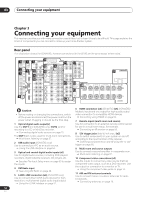
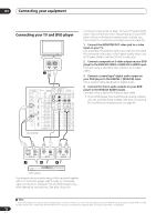
03 Connecting your equipment Chapter 3 Connecting your equipment This receiver provides you with many connection possibilities, but it doesn't have to be difficult. This page explains the kinds of components you can connect to make up your home theater system. Rear panel This illustration shows the VSX-84TXSi, however connections for the 82TXS are the same except where noted. 1 MULTI-ROOM & SOURCE / REC SEL 5 OUT1 ROOM3 S400 (ZONE3) (AUDIO) OUT2 11 7IR MULTI-ROOM & SOURCE MAIN ROOM(ZONE1) FM UNBAL 75 Ω IN1 ROOM2(ZONE2) 12 MONITOR OUT OUT IN2 2 3 S400 USB AUDIO IN 6 IN 1 (SAT) IN 2 (DVR/ 8 13 HDMI IN1 12 V TRIGGER 1 2 (DC OUT 12V TOTAL 50 mA MAX) 9ROOM2 IN2 (ZONE2) MULTI-ROOM & SOURCE MONITOR OUT IN 1 IN 2 VCR 1) IN 3 10IN 1 Y OUT IN 1 (DVD/LD) Y IN 2 (TV) (DVR/ 12 VCR 2) ASSIGNABLE IN 4 (CD-R) 14 ASSIGNABLE IN 1 1 2 (DVD/ LD) IN3 PB PR IN4 IN 2 PB PR IN 3 IN 2 (CD) Y Y 14 ANTENNA AUDIO PHONO AM LOOP PRE OUT 17R L FRONT IN 9MULTI-ROOM & SOURCE R ROOM2(ZONE2) L CD SUB W. CENTER OUT DVD/ LD IN TV IN SAT IN IN OUT CD-R/ TAPE IN R R L SURROUND SURROUND BACK (Single) L VIDEO / GAME1 IN 15FR SUB W. FL 18iPod CENTER SPEAKERS 20 IN A R FRONT L OUT DVR/ VCR 1 IN SURROUND 19 R L 4 IN PB OUT PB XM PR PR OUT DVR/ VCR 2 IN R SURROUND L 16 BACK MULTI CH IN RS-232C OUT IN DIGITAL ASSIGNABLE 1 3 S - VIDEO VIDEO COMPONENT VIDEO VIDEO R L AUDIO CONTROL CENTER 21 AC OUTLET SWITCHED 100 W(0.8A) MAX R SURROUND L SURROUND R BACK / L(Single) B SELECTABLE Caution • Before making or changing the connections, switch off the power and disconnect the power cord from the power outlet. Plugging in should be the final step. 1 Optical digital audio output(s) Use the OUT1 and (VSX-84TXSi only) OUT2 jack for recording to a CD or MiniDisc recorder. Connecting digital audio sources on page 15. The OUT1 jack is also used for multi-room connections. Multi-room listening on page 57. 2 USB audio input (VSX-84TXSi only) Use to connect your PC as an audio source. Using the USB interface on page 54. 3 Optical and coaxial digital audio inputs (x6) Use for digital audio sources, including DVD players/ recorders, digital satellite receivers, CD players, etc. See also The Input Setup menu on page 63 to assign the inputs. 4 XM Radio input See Using XM Radio on page 48. 5 S-400 i.LINK connectors (x2) (VSX-84TXSi only) Use to connect other i.LINK audio devices for highresolution, multichannel digital audio input/output. Using the i.LINK interface on page 51. 6 HDMI connectors (x4) (VSX-82TXS) (x5) (VSX-84TXSi) Multiple inputs and one output for high-quality audio/ video connection to compatible HDMI devices. Connecting using HDMI on page 50. 7 Remote inputs (multi-room and source) Use for connection to an external remote control sensor for use in a multi-room setup, for example. Connecting an IR receiver on page 59. 8 12V trigger jacks (total 50 mA max.) (x2) Use to switch components in your system on and off according to the input function of the receiver. Switching components on and off using the 12 volt trigger on page 60. 9 Multi-room and source outputs Use to connect a second amplifier in a separate room. Multi-room listening on page 57. 10 Component video connections (x4) Use the inputs to connect any video source that has component video output, such as a DVD recorder. Use the output for connection to a monitor or TV. Using the component video jacks on page 14. 11 AM and FM antenna terminals Use to connect indoor or outdoor antennas for radio broadcasts. Connecting antennas on page 19. 10 En
-
 1
1 -
2
-
3
-
4
-
 5
5 -
 6
6 -
 7
7 -
 8
8 -
 9
9 -
 10
10 -
 11
11 -
 12
12 -
 13
13 -
 14
14 -
 15
15 -
16
-
17
-
18
-
19
-
20
-
21
-
22
-
23
-
24
-
25
-
26
-
27
-
28
-
29
-
30
-
31
-
32
-
33
-
34
-
35
-
36
-
37
-
38
-
39
-
40
-
41
-
42
-
43
-
44
-
45
-
46
-
47
-
48
-
49
-
50
-
51
-
52
-
53
-
54
-
55
-
56
-
57
-
58
-
59
-
60
-
61
-
62
-
63
-
64
-
65
-
66
-
67
-
68
-
69
-
70
-
71
-
72
-
73
-
74
-
75
-
76
-
77
-
78
-
79
-
80
-
81
-
82
-
83
-
84
-
85
-
86
-
87
-
88
-
89
-
90
-
91
-
92
 |
 |
