Pioneer VSX 82TXS Owner's Manual - Page 13
your set-top box to the DIGITAL 1 SAT input. - computer set up
 |
UPC - 012562820453
View all Pioneer VSX 82TXS manuals
Add to My Manuals
Save this manual to your list of manuals |
Page 13 highlights
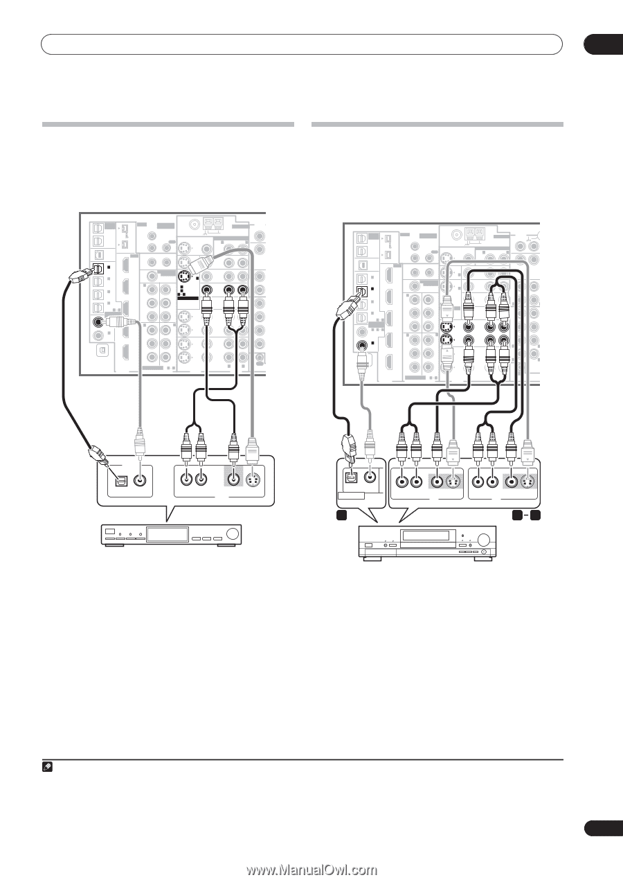
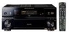
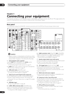
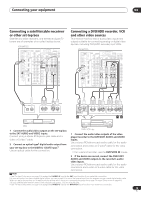
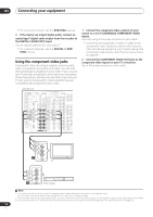
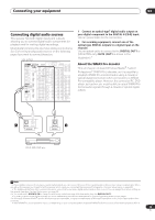
Connecting your equipment 03 Connecting a satellite/cable receiver or other set-top box Satellite and cable receivers, and terrestrial digital TV tuners are all examples of so-called 'set-top boxes'. VSX-84TXSi MULTI-ROOM & SOURCE / REC SEL OUT1 ROOM3 (ZONE3) OUT2 S400 (AUDIO) IR MULTI-ROOM & SOURCE MAIN ROOM(ZONE1) IN1 ROOM2(ZONE2) OUT FM UNBAL 75 Ω MONITOR OUT USB AUDIO IN S400 IN 1 (SAT) IN 2 (DVR/ VCR 1) IN 3 (DVR/ VCR 2) IN2 HDMI 12 V TRIGGER IN1 1 2 IN 1 (DC OUT 12V TOTAL 50 mA MAX) ROOM2 IN2 (ZONE2) MULTI-ROOM & SOURCE MONITOR OUT IN 2 IN 1 OUT IN 1 (DVD/LD) Y Y IN 2 (TV) 12 ASSIGNABLE IN 4 (CD-R) 14 ASSIGNABLE IN 1 1 2 (DVD/ LD) IN 2 (CD) IN3 PB PR IN4 IN 2 Y PB PR IN 3 Y ANTENNA AUDIO PHONO AM LOOP IN MULTI-ROOM & SOURCE R ROOM2(ZONE2) L CD OUT IN DVD/ LD IN TV IN SAT IN VIDEO / GAME1 IN OUT DVR/ VCR 1 IN OUT CD-R/ TAPE IN R FR F SUB W. SURROUND R IN XM OUT DIGITAL PB PB PR PR OUT DVR/ VCR 2 IN ASSIGNABLE 1 3 S - VIDEO VIDEO COMPONENT VIDEO VIDEO R L AUDIO R SURR OUT CONTROL Connecting a DVD/HDD recorder, VCR and other video sources This receiver has two sets of audio/video inputs and outputs suitable for connecting analog or digital video devices, including DVD/HDD recorders and VCRs. VSX-84TXSi MULTI-ROOM & SOURCE / REC SEL OUT1 ROOM3 (ZONE3) OUT2 S400 (AUDIO) IR MULTI-ROOM & SOURCE MAIN ROOM(ZONE1) IN1 ROOM2(ZONE2) OUT FM UNBAL 75 Ω MONITOR OUT USB AUDIO IN S400 IN 1 (SAT) IN 2 (DVR/ VCR 1) IN 3 (DVR/ VCR 2) IN2 HDMI 12 V TRIGGER IN1 1 2 IN 1 (DC OUT 12V TOTAL 50 mA MAX) ROOM2 MULTI-ROOM & SOURCE MONITOR IN 2 IN2 (ZONE2) OUT IN 1 OUT IN 1 (DVD/LD) Y Y IN 2 (TV) 12 ASSIGNABLE IN 4 IN3 PB PB (CD-R) 14 ASSIGNA- BLE PR PR IN 1 1 2 (DVD/ LD) IN4 IN 2 IN 3 IN 2 (CD) Y Y ANTENNA AUDIO PHONO AM LOOP IN MULTI-ROOM & SOURCE R ROOM2(ZONE2) L CD OUT IN DVD/ LD IN TV IN SAT IN VIDEO / GAME1 IN OUT DVR/ VCR 1 IN OUT CD-R/ TAPE IN R L FR FL SUB W. CENTER SURROUND R L IN XM OUT DIGITAL PB PB PR PR OUT DVR/ VCR 2 IN ASSIGNABLE 1 3 S - VIDEO VIDEO COMPONENT VIDEO VIDEO R L AUDIO R SURROUND L BACK MULTI CH IN OUT CONTROL DIGITAL OUT R AUDIO L VIDEO AV OUT S-VIDEO OPTICAL COAXIAL DIGITAL OUT 3 R AUDIO L VIDEO AV OUT S-VIDEO R AUDIO L AV IN VIDEO S-VIDEO 12 STB 1 Connect the audio/video outputs on the set-top box to the SAT AUDIO and VIDEO inputs. Connect using a stereo RCA/phono jack cable and a video or S-video1 cable. 2 Connect an optical-type2 digital audio output from your set-top box to the DIGITAL 1 (SAT) input.3 Use an optical cable for the connection. DVR, VCR, etc. 1 Connect the audio/video outputs of the video player/recorder to the DVR/VCR1 AUDIO and VIDEO inputs. Use a stereo RCA/phono jack audio cable for the audio connection and a video or S-video4 cable for the video connection. • For a second recorder, use the DVR/VCR2 IN inputs. 2 If the device can record, connect the DVR/VCR1 AUDIO and VIDEO outputs to the recorder's audio/ video inputs. Use a stereo RCA/phono jack audio cable for the audio connection and a video or S-video cable for the video connection. Note 1 See The Input Setup menu on page 63 to assign the S-VIDEO 2 input to the SAT input function if you make this connection. 2 If your set-top box only has a coaxial digital output, you can connect it to one of the coaxial inputs on this receiver using a coaxial digital audio cable. When you set up the receiver you'll need to tell the receiver which input you connected the set-top box to (see The Input Setup menu on page 63). 3 If your satellite/cable receiver doesn't have a digital audio output, you can skip this step. 4 See The Input Setup menu on page 63 to assign the S-VIDEO 2 input to the DVR/VCR1 input function if you make this connection. 13 En
-
 1
1 -
2
-
3
-
4
-
5
-
6
-
7
-
 8
8 -
 9
9 -
 10
10 -
 11
11 -
 12
12 -
 13
13 -
 14
14 -
 15
15 -
 16
16 -
 17
17 -
 18
18 -
19
-
20
-
21
-
22
-
23
-
24
-
25
-
26
-
27
-
28
-
29
-
30
-
31
-
32
-
33
-
34
-
35
-
36
-
37
-
38
-
39
-
40
-
41
-
42
-
43
-
44
-
45
-
46
-
47
-
48
-
49
-
50
-
51
-
52
-
53
-
54
-
55
-
56
-
57
-
58
-
59
-
60
-
61
-
62
-
63
-
64
-
65
-
66
-
67
-
68
-
69
-
70
-
71
-
72
-
73
-
74
-
75
-
76
-
77
-
78
-
79
-
80
-
81
-
82
-
83
-
84
-
85
-
86
-
87
-
88
-
89
-
90
-
91
-
92
 |
 |