Pioneer VSX 82TXS Owner's Manual - Page 60
receiver to link it to the IR receiver.
 |
UPC - 012562820453
View all Pioneer VSX 82TXS manuals
Add to My Manuals
Save this manual to your list of manuals |
Page 60 highlights
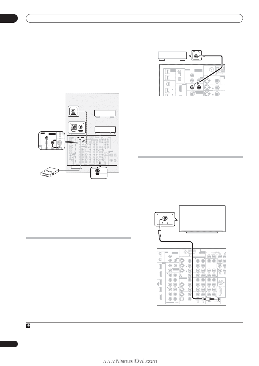
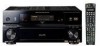
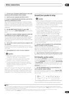
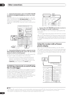
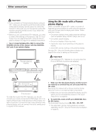
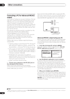
08 Other connections 1 Connect the IR receiver sensor to the MULTI-ROOM & SOURCE IR IN (MAIN ROOM) jack on the rear of this receiver. If you also plan to use a separate IR receiver in the sub room, connect this to the ROOM2(ZONE2) jack. This will allow you to use the sub room remote control as explained in (VSX-84TXSi only) Sub remote control unit on page 26. Closet or shelving unit Non-Pioneer IR component IN CONTROL Pioneer component IR MULTI-ROOM & SOURCE MAIN ROOM(ZONE1) IN1 ROOM2(ZONE2) OUT IN2 HDMI N1 12 V TRIGGER 1 2 FM UNBAL 7 MONIT OUT IN 1 IN OUT MULTI-ROOM & SOURCE / REC SEL OUT1 ROOM3 (ZONE3) OUT2 S400 (AUDIO) IR MULTI-ROOM & SOURCE MAIN ROOM(ZONE1) IN1 ROOM2(ZONE2) OUT FM UNBAL 75 Ω MONITOR OUT USB AUDIO IN S400 IN 1 (SAT) IN 2 (DVR/ VCR 1) IN 3 (DVR/ VCR 2) IN2 HDMI 12 V TRIGGER IN1 1 2 IN 1 (DC OUT 12V TOTAL 50 mA MAX) ROOM2 MULTI-ROOM & SOURCE MONITOR IN 2 IN2 (ZONE2) OUT IN 1 OUT IN 1 (DVD/LD) Y Y IN 2 (TV) 12 ASSIGNABLE IN 4 (CD-R) 14 ASSIGNABLE IN 1 1 2 (DVD/ LD) IN 2 (CD) IN3 PB PR IN4 IN 2 Y PB PR IN 3 Y ANTENNA AUDIO PHONO AM LOOP IN MULTI-ROOM & SOURCE R ROOM2(ZONE2) L CD PRE OUT R L FRONT SUB W. CENTER OUT DVD/ LD IN TV IN SAT IN IN OUT CD-R/ TAPE IN R R L SURROUND SURROUND BACK (Single) L VIDEO / GAME1 IN FR FL iPod SUB W. CENTER SPEAKERS IN A R FRONT L OUT DVR/ VCR 1 IN SURROUND R L IN XM OUT DIGITAL PB PB PR PR OUT DVR/ VCR 2 IN ASSIGNABLE 1 3 S - VIDEO VIDEO COMPONENT VIDEO VIDEO R L AUDIO R SURROUND L BACK RS-232C MULTI CH IN OUT IN CONTROL SURROUND L BACK IR receiver MULTI CH OUT IN CONTROL 2 Connect the IR IN jack of another component to the MULTI-ROOM & SOURCE IR OUT jack on the rear of this receiver to link it to the IR receiver. Please see the manual supplied with your IR receiver for the type of cable necessary for the connection. • If you want to link a Pioneer component to the IR receiver, see Operating other Pioneer components with this unit's sensor on page 76 to connect to the CONTROL jacks instead of the IR OUT jack. Switching components on and off using the 12 volt trigger You can connect components in your system (such as a screen or projector) to this receiver so that they switch on or off using 12 volt triggers when you select an input function. However, you must specify which input functions switch on the trigger using the The Input Setup menu on page 63. Note that this will only work with components that have a standby mode. 12V TRIGGER MULTI-ROOM & SOURCE / REC SEL OUT1 ROOM3 (ZONE3) OUT2 S400 (AUDIO) IR MULTI-ROOM & SOURCE MAIN ROOM(ZONE1) IN1 ROOM2(ZONE2) OUT USB AUDIO IN S400 IN2 HDMI IN1 12 V TRIGGER 1 2 IN 1 (SAT) IN 2 (DVR/ (DC OUT 12V TOTAL 50 mA MAX) ROOM2 IN2 (ZONE2) MULTI-ROOM & SOURCE MONITOR OUT FM UNBAL 75 Ω MONITOR OUT IN 1 IN 2 AM MULTI-R R OUT DVD/ LD IN TV IN • Connect the 12V TRIGGER jack of this receiver to the 12V trigger of another component. Use a cable with a mono mini-plug on each end for the connection. • The trigger maximum power is DC OUT 12 V / 50 mA. After you've specified the input functions that will switch on the trigger, you'll be able to switch the component on or off just by pressing the input function(s) you've set on page 63. Using this receiver with a Pioneer plasma display If you have a Pioneer plasma display, you can use an SR+ cable1 to connect it to this unit and take advantage of various convenient features, such as automatic video input switching of the plasma display when the input is changed.2 CONTROL OUT Pioneer plasma display S400 (AUDIO) IR MULTI-ROOM & SOURCE MAIN ROOM(ZONE1) IN1 ROOM2(ZONE2) OUT FM UNBAL 75 Ω MONITOR OUT IN2 S400 HDMI 12 V TRIGGER IN1 1 2 (DC OUT 12V TOTAL 50 mA MAX) IN 1 ROOM2 IN2 (ZONE2) IN 1 Y MULTI-ROOM & SOURCE MONITOR OUT IN 2 OUT IN 1 (DVD/LD) Y IN 2 (TV) 12 ASSIGNABLE IN3 PB PB 4 NA- PR 2 IN4 IN 2 Y PR IN 3 Y ANTENNA AUDIO PHONO AM LOOP IN MULTI-ROOM & SOURCE R ROOM2(ZONE2) L CD OUT IN PRE OUT R L SUB W. C DVD/ LD IN TV IN SAT IN VIDEO / GAME1 IN OUT DVR/ VCR 1 IN OUT CD-R/ TAPE R L IN R L FR FL iPod IN SUB W. CENTER SURROUND R L OUT DIGITAL PB PB PR PR OUT DVR/ VCR 2 IN ASSIGNABLE 1 3 S - VIDEO VIDEO COMPONENT VIDEO VIDEO R L AUDIO R SURROUND L BACK RS-232C MULTI CH IN OUT IN CONTROL Note 1 The 3-ringed SR+ cable from Pioneer is commercially available under the part number ADE7095. Contact the Pioneer Customer Support division for more information on obtaining an SR+ cable (you can also use a commercially available 3-ringed mini phone plug for the connection). 2 This receiver is compatible with all SR+ equipped Pioneer plasma displays from 2003 onward. 60 En
-
 1
1 -
2
-
3
-
4
-
5
-
6
-
7
-
8
-
9
-
10
-
11
-
12
-
13
-
14
-
15
-
16
-
17
-
18
-
19
-
20
-
21
-
22
-
23
-
24
-
25
-
26
-
27
-
28
-
29
-
30
-
31
-
32
-
33
-
34
-
35
-
36
-
37
-
38
-
39
-
40
-
41
-
42
-
43
-
44
-
45
-
46
-
47
-
48
-
49
-
50
-
51
-
52
-
53
-
54
-
 55
55 -
 56
56 -
 57
57 -
 58
58 -
 59
59 -
 60
60 -
 61
61 -
 62
62 -
 63
63 -
 64
64 -
 65
65 -
66
-
67
-
68
-
69
-
70
-
71
-
72
-
73
-
74
-
75
-
76
-
77
-
78
-
79
-
80
-
81
-
82
-
83
-
84
-
85
-
86
-
87
-
88
-
89
-
90
-
91
-
92
 |
 |