Pioneer VSX 82TXS Owner's Manual - Page 58
of this receiver.
 |
UPC - 012562820453
View all Pioneer VSX 82TXS manuals
Add to My Manuals
Save this manual to your list of manuals |
Page 58 highlights
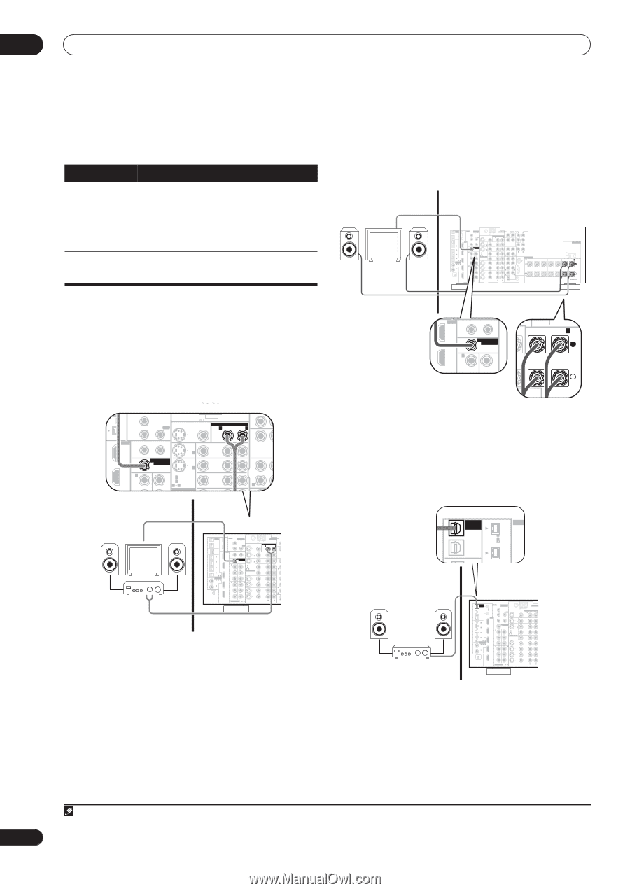
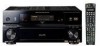
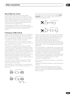
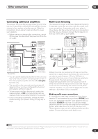
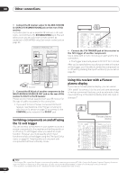
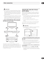
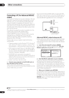
08 Other connections Multi-room listening options The following table shows what you can listen to in each sub room: Sub room Input sources available ROOM2 (ZONE2) iPod, XM Radio, the built-in tuner and other analog audio sources (except MULTI CH IN). With video sources, only composite video is possible. Please note that the XM-Radio function is not available for sub room (ROOM2) listening when using the multi-room feature with the VSX-82TXS. ROOM3 (ZONE3) Only digital audio sources (the input source must already be assigned using the The Input Setup menu on page 63) are available. Basic multi-room setup (ROOM 2) 1 Connect a separate amplifier to the MULTI-ROOM & SOURCE OUT jacks and a TV monitor to the MULTIROOM & SOURCE MONITOR OUT jacks, both on the rear of this receiver. You should have a pair of speakers attached to the sub room amplifier as shown in the following illustration. • Connect a TV monitor to the MULTI-ROOM & SOURCE MONITOR OUT jacks on the rear of this receiver. You should have a pair of speakers attached to the surround back speaker terminals as shown below. Sub room Main room MULTI-ROOM & SOURCE / REC SEL OUT1 ROOM3 (ZONE3) OUT2 S400 (AUDIO) IR MULTI-ROOM & SOURCE MAIN ROOM(ZONE1) IN1 ROOM2(ZONE2) OUT FM UNBAL 75 Ω MONITOR OUT USB AUDIO IN S400 IN 1 (SAT) IN 2 (DVR/ VCR 1) IN 3 (DVR/ VCR 2) IN2 HDMI 12 V TRIGGER IN1 1 2 IN 1 (DC OUT 12V TOTAL 50 mA MAX) ROOM2 MULTI-ROOM & SOURCE MONITOR IN 2 IN2 (ZONE2) OUT IN 1 OUT IN 1 (DVD/LD) Y Y IN 2 (TV) 12 ASSIGNABLE IN 4 (CD-R) 14 ASSIGNABLE IN 1 1 2 (DVD/ LD) IN 2 (CD) IN3 PB PR IN4 IN 2 Y PB PR IN 3 Y ANTENNA AUDIO PHONO AM LOOP IN MULTI-ROOM & SOURCE R ROOM2(ZONE2) L CD PRE OUT R L FRONT SUB W. CENTER OUT DVD/ LD IN TV IN SAT IN IN OUT CD-R/ TAPE IN R R L SURROUND SURROUND BACK (Single) L VIDEO / GAME1 IN FR FL iPod SUB W. CENTER SPEAKERS IN A R FRONT L OUT DVR/ VCR 1 IN SURROUND R L IN XM OUT DIGITAL PB PB PR PR OUT DVR/ VCR 2 IN ASSIGNABLE 1 3 S - VIDEO VIDEO COMPONENT VIDEO VIDEO R L AUDIO R SURROUND L BACK RS-232C MULTI CH IN OUT IN CONTROL CENTER AC OUTLET SWITCHED 100 W(0.8A) MAX R SURROUND L SURROUND BACK / R L(Single) B SELECTABLE S400 HDMI 12 V TRIGGER IN1 1 2 (DC OUT 12V TOTAL 50 mA MAX) L SURROUND R BACK / L(Single) B ROOM2 MULTI-ROOM & SOURCE IN2 (ZONE2) MONITOR OUT IN 1 OUT IN Y Y IN S400 (AUDIO) MAIN ROOM(ZONE1) IN1 ROOM2(ZONE2) OUT FM UNBAL 75 Ω MONITOR OUT IN2 S400 HDMI 12 V TRIGGER IN1 1 2 IN 1 (DC OUT 12V TOTAL 50 mA MAX) ROOM2 MULTI-ROOM & SOURCE MONITOR IN 2 IN2 (ZONE2) OUT IN 1 OUT IN 1 (DVD/LD) Y Y IN 2 (TV) 12 ASSIGNABLE PHONO AM LOOP IN MULTI-ROOM & SOURCE R ROOM2(ZONE2) L CD OUT IN DVD/ LD IN TV IN SAT IN OUT CD-R/ TAPE IN R FR FL Sub room Main room MULTI-ROOM & SOURCE / REC SEL OUT1 ROOM3 (ZONE3) OUT2 S400 (AUDIO) IR MULTI-ROOM & SOURCE MAIN ROOM(ZONE1) IN1 ROOM2(ZONE2) OUT FM UNBAL 75 Ω MONITOR OUT USB AUDIO IN S400 IN 1 (SAT) IN 2 (DVR/ VCR 1) IN 3 (DVR/ VCR 2) IN2 HDMI 12 V TRIGGER IN1 1 2 IN 1 (DC OUT 12V TOTAL 50 mA MAX) ROOM2 MULTI-ROOM & SOURCE MONITOR IN 2 IN2 (ZONE2) OUT IN 1 OUT IN 1 (DVD/LD) Y Y IN 2 (TV) 12 ASSIGNABLE IN 4 (CD-R) 14 ASSIGNABLE IN 1 1 2 (DVD/ LD) IN3 PB PR IN4 IN 2 PB PR IN 3 IN 2 (CD) Y Y ANTENNA AU PHONO AM LOOP IN MULTI-ROOM & SOURCE R ROOM2(ZONE2) L CD OUT IN DVD/ LD IN TV IN SAT IN VIDEO / GAME1 IN OUT DVR/ VCR 1 IN OUT CD-R/ TAPE IN R FR SUB W. SURROUND R IN XM OUT DIGITAL PB PB PR PR OUT DVR/ VCR 2 IN ASSIGNABLE 1 3 S - VIDEO VIDEO COMPONENT VIDEO VIDEO R L AUDIO RS OU CONTR Surround Back System multi-room setup (ROOM 2) You must select MR&S in Surround back speaker setting on page 36 to use this setup. Note that the sound in the sub room will be temporarily interrupted when controlling the main room (for example, changing the input source or starting playback). Secondary multi-room setup (ROOM 3) • Connect a separate amplifier to the OUT1 ROOM3 (ZONE3) digital output on the rear of this receiver. The amplifier must have an optical digital input to make this connection. This will allow you to hear the digital output of a component in a second sub room.1 Sub room (ROOM 3) MULTI-ROOM & SOURCE / REC SEL OUT1 ROOM3 (ZONE3) OUT2 S400 (AUDIO) USB S400 IR IN1 IN2 Main room DIGITAL IN MULTI-ROOM & SOURCE / REC SEL OUT1 ROOM3 (ZONE3) OUT2 S400 (AUDIO) IR MULTI-ROOM & SOURCE MAIN ROOM(ZONE1) IN1 ROOM2(ZONE2) OUT FM UNBAL 75 Ω MONITOR OUT USB AUDIO IN S400 IN 1 (SAT) IN 2 (DVR/ VCR 1) IN 3 (DVR/ VCR 2) IN2 HDMI 12 V TRIGGER IN1 1 2 IN 1 (DC OUT 12V TOTAL 50 mA MAX) ROOM2 MULTI-ROOM & SOURCE MONITOR IN 2 IN2 (ZONE2) OUT IN 1 OUT IN 1 (DVD/LD) Y Y IN 2 (TV) 12 ASSIGNABLE IN 4 (CD-R) 14 ASSIGNABLE IN 1 1 2 (DVD/ LD) IN3 PB PR IN4 IN 2 PB PR IN 3 IN 2 (CD) Y Y PB PB OUT IN XM PR PR ANTENNA AM LOOP MULTI-ROOM & SOURCE R ROOM2(ZONE2) L OUT DVD/ LD IN TV IN C T SAT IN VIDEO / GAME1 IN OUT DVR/ VCR 1 IN OUT DVR/ VCR 2 IN DIGITAL ASSIGNABLE 1 3 S - VIDEO VIDEO COMPONENT VIDEO VIDEO R L AUDIO Note 1 Only one sub room is possible if you connect the OUT1 ROOM3 (ZONE3) digital output to your second sub room. 58 En
-
 1
1 -
2
-
3
-
4
-
5
-
6
-
7
-
8
-
9
-
10
-
11
-
12
-
13
-
14
-
15
-
16
-
17
-
18
-
19
-
20
-
21
-
22
-
23
-
24
-
25
-
26
-
27
-
28
-
29
-
30
-
31
-
32
-
33
-
34
-
35
-
36
-
37
-
38
-
39
-
40
-
41
-
42
-
43
-
44
-
45
-
46
-
47
-
48
-
49
-
50
-
51
-
52
-
 53
53 -
 54
54 -
 55
55 -
 56
56 -
 57
57 -
 58
58 -
 59
59 -
 60
60 -
 61
61 -
 62
62 -
 63
63 -
64
-
65
-
66
-
67
-
68
-
69
-
70
-
71
-
72
-
73
-
74
-
75
-
76
-
77
-
78
-
79
-
80
-
81
-
82
-
83
-
84
-
85
-
86
-
87
-
88
-
89
-
90
-
91
-
92
 |
 |