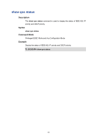
TP-Link TL-SG2424P TL-SG2424P V1 CLI Reference Guide - Page 90
qos queue mode, User Guidelines, Example, Description, Syntax, Parameter
 |
View all TP-Link TL-SG2424P manuals
Add to My Manuals
Save this manual to your list of manuals |
Page 90 highlights
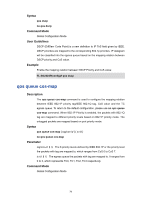
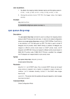
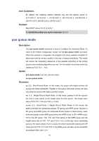
User Guidelines By default, the mapping relation between tag and the egress queue is: (0-7)-CoS 0, (8-15)-CoS 1, (16-23)-CoS 2, (24-31)-CoS 3, (32-39)-CoS 4, (40-47)-CoS 5, (48-55)-CoS 6, (56-63)-CoS 7. Example Map DSCP values 10-12 to CoS 2: TL-SG2424P(config)# qos queue dscp-map 10-12 2 qos queue mode Description The qos queue mode command is used to configure the Schedule Mode. To return to the default configuration, please use no qos queue mode command. When the network is congested, the program that many packets complete for resources must be solved, usually in the way of queue scheduling. The switch will control the forwarding sequence of the packets according to the priority queues and scheduling algorithms you set. On this switch, the priority levels are labeled as TC0, TC1... TC3. Syntax qos queue mode { sp | wrr | sp+wrr | equ } no qos queue mode Parameter sp ii Strict-Priority Mode. In this mode, the queue with higher priority will occupy the whole bandwidth. Packets in the queue with lower priority are sent only when the queue with higher priority is empty. wrr ii Weight Round Robin Mode. In this mode, packets in all the queues are sent in order based on the weight value for each queue. The weight value ratio of TC0, TC1, TC2 and TC3 is 1:2:4:8. sp+wrr ii Strict-Priority + Weight Round Robin Mode. In this mode, the switch provides two scheduling groups, SP group and WRR group. Queues in SP group and WRR group are scheduled strictly based on Strict-Priority mode while the queues inside WRR group follow the WRR mode. In SP + WRR mode, TC3 is the SP group; TC0, TC1 and TC2 belong to the WRR group and the weight value ratio of TC0, TC1 and TC2 is 1:2:4. In this way, when scheduling queues, the switch allows TC3 to occupy the whole bandwidth following the SP mode and the TC0, TC1 and TC2 in the WRR group will take up the bandwidth according to their ratio 1:2:4. 80
-
 1
1 -
2
-
3
-
4
-
5
-
6
-
7
-
8
-
9
-
10
-
11
-
12
-
13
-
14
-
15
-
16
-
17
-
18
-
19
-
20
-
21
-
22
-
23
-
24
-
25
-
26
-
27
-
28
-
29
-
30
-
31
-
32
-
33
-
34
-
35
-
36
-
37
-
38
-
39
-
40
-
41
-
42
-
43
-
44
-
45
-
46
-
47
-
48
-
49
-
50
-
51
-
52
-
53
-
54
-
55
-
56
-
57
-
58
-
59
-
60
-
61
-
62
-
63
-
64
-
65
-
66
-
67
-
68
-
69
-
70
-
71
-
72
-
73
-
74
-
75
-
76
-
77
-
78
-
79
-
80
-
81
-
82
-
83
-
84
-
 85
85 -
 86
86 -
 87
87 -
 88
88 -
 89
89 -
 90
90 -
 91
91 -
 92
92 -
 93
93 -
 94
94 -
 95
95 -
96
-
97
-
98
-
99
-
100
-
101
-
102
-
103
-
104
-
105
-
106
-
107
-
108
-
109
-
110
-
111
-
112
-
113
-
114
-
115
-
116
-
117
-
118
-
119
-
120
-
121
-
122
-
123
-
124
-
125
-
126
-
127
-
128
-
129
-
130
-
131
-
132
-
133
-
134
-
135
-
136
-
137
-
138
-
139
-
140
-
141
-
142
-
143
-
144
-
145
-
146
-
147
-
148
-
149
-
150
-
151
-
152
-
153
-
154
-
155
-
156
-
157
-
158
-
159
-
160
-
161
-
162
-
163
-
164
-
165
-
166
-
167
-
168
 |
 |