Yamaha YSP-5600 Owners Manual - Page 9
The unit rear, IR-IN, IR-OUT, and RS-232C jacks - firmware
 |
View all Yamaha YSP-5600 manuals
Add to My Manuals
Save this manual to your list of manuals |
Page 9 highlights
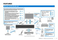
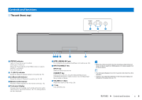
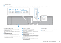
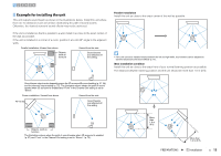
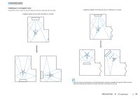
The unit (rear) • So that the HDMI and NETWORK jacks may be easily located, the illustration of the rear of the unit used in this manual shows their respective positions with the labels used on the unit itself. 12 3 4 5 67 SYSTEM SUBWOOFER CONNECTOR OUT R L AUX1 AUX2 TV OPTICAL IR-IN IR-OUT UPDATE ONLY RS-232C IN 1 (HDCP2.2) IN 2 IN 3 8 IN 1 (HDCP2.2) IN 2 IN 3 IN 4 HDMI OUT (ARC) IN 4 HDMI OUT (ARC) 9 0 NETWORK AC IN a 1 SYSTEM CONNECTOR jack Connect to a Yamaha subwoofer so that the subwoofer functions according to the unit' power on and off (p. 25). 2 SUBWOOFER OUT jack For connecting to the subwoofer using a wired connection (p. 25). 3 AUX1 analog input jacks For connecting to a playback device equipped with the analog audio output jacks (p. 24). 4 AUX2 digital coaxial input jack For connecting to a playback device equipped with a digital coaxial audio output jack (p. 24). SYSTEM SUBWOOFER CONNECTOR OUT R L AUX1 AUX2 TV OPTICAL IR-IN IR-OUT UPDATE ONLY RS-232C NETWORK 5 TV and OPTICAL jacks For connecting to a playback device equipped with an digital optical audio output jack (p. 22, 23). 6 IR-IN, IR-OUT, and RS-232C jacks They are control expansion jacks for commercial use only. 7 UPDATE ONLY jack Use to update this unit's firmware (p. 87). 8 HDMI IN 1-4 jacks For connecting an HDMI-compatible playback device such as a BD/DVD player, a satellite and cable TV tuner, and a game console (p. 23). 9 HDMI OUT (ARC) jack For connecting to an HDMI-compatible TV and outputting video/audio signals (p. 22). 0 NETWORK jack For connecting to a network with a network cable (p. 51). A AC IN jack Connect the supplied power cable (p. 26). FEATURES ➤ Controls and functions En 9
-
 1
1 -
2
-
3
-
 4
4 -
 5
5 -
 6
6 -
 7
7 -
 8
8 -
 9
9 -
 10
10 -
 11
11 -
 12
12 -
 13
13 -
 14
14 -
15
-
16
-
17
-
18
-
19
-
20
-
21
-
22
-
23
-
24
-
25
-
26
-
27
-
28
-
29
-
30
-
31
-
32
-
33
-
34
-
35
-
36
-
37
-
38
-
39
-
40
-
41
-
42
-
43
-
44
-
45
-
46
-
47
-
48
-
49
-
50
-
51
-
52
-
53
-
54
-
55
-
56
-
57
-
58
-
59
-
60
-
61
-
62
-
63
-
64
-
65
-
66
-
67
-
68
-
69
-
70
-
71
-
72
-
73
-
74
-
75
-
76
-
77
-
78
-
79
-
80
-
81
-
82
-
83
-
84
-
85
-
86
-
87
-
88
-
89
-
90
-
91
-
92
-
93
-
94
-
95
-
96
-
97
-
98
-
99
-
100
-
101
-
102
-
103
-
104
-
105
-
106
-
107
-
108
-
109
-
110
 |
 |
