ZyXEL ES-315 User Guide - Page 134
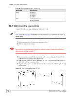
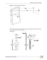
Wall-mounting Instructions, for the size of screws to use and how far apart to, place them.
 |
View all ZyXEL ES-315 manuals
Add to My Manuals
Save this manual to your list of manuals |
Page 134 highlights
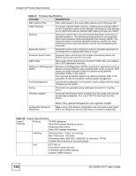
Chapter 22 Product Specifications Table 49 Standards Supported (continued) STANDARD DESCRIPTION Safety UL 60950-1 CSA 60950-1 EN 60950-1 IEC 60950-1 EMC FCC Part 15 (Class B) CE EMC (Class B) 22.2 Wall-mounting Instructions Complete the following steps to hang your Switch on a wall. " See Table 46 on page 131 for the size of screws to use and how far apart to place them. 1 Select a position free of obstructions on a sturdy wall. 2 Drill two holes for the screws. 1 Be careful to avoid damaging pipes or cables located inside the wall when drilling holes for the screws. 3 Do not insert the screws all the way into the wall. Leave a small gap of about 0.5 cm between the heads of the screws and the wall. 4 Make sure the screws are snugly fastened to the wall. They need to hold the weight of the Switch with the connection cables. 5 Align the holes on the back of the Switch with the screws on the wall. Hang the Switch on the screws. Figure 70 Wall-mounting Example: ES-315 134 ES-315/ES-315-F User's Guide
-
 1
1 -
2
-
3
-
4
-
5
-
6
-
7
-
8
-
9
-
10
-
11
-
12
-
13
-
14
-
15
-
16
-
17
-
18
-
19
-
20
-
21
-
22
-
23
-
24
-
25
-
26
-
27
-
28
-
29
-
30
-
31
-
32
-
33
-
34
-
35
-
36
-
37
-
38
-
39
-
40
-
41
-
42
-
43
-
44
-
45
-
46
-
47
-
48
-
49
-
50
-
51
-
52
-
53
-
54
-
55
-
56
-
57
-
58
-
59
-
60
-
61
-
62
-
63
-
64
-
65
-
66
-
67
-
68
-
69
-
70
-
71
-
72
-
73
-
74
-
75
-
76
-
77
-
78
-
79
-
80
-
81
-
82
-
83
-
84
-
85
-
86
-
87
-
88
-
89
-
90
-
91
-
92
-
93
-
94
-
95
-
96
-
97
-
98
-
99
-
100
-
101
-
102
-
103
-
104
-
105
-
106
-
107
-
108
-
109
-
110
-
111
-
112
-
113
-
114
-
115
-
116
-
117
-
118
-
119
-
120
-
121
-
122
-
123
-
124
-
125
-
126
-
127
-
128
-
 129
129 -
 130
130 -
 131
131 -
 132
132 -
 133
133 -
 134
134 -
 135
135 -
 136
136 -
 137
137 -
 138
138 -
 139
139 -
140
-
141
-
142
-
143
-
144
-
145
-
146
-
147
-
148
-
149
-
150
-
151
-
152
-
153
-
154
-
155
-
156
-
157
-
158
-
159
-
160
-
161
-
162
-
163
-
164
-
165
-
166
 |
 |
