ZyXEL ES-315 User Guide - Page 82
MVR Configuration Example, Table 25
 |
View all ZyXEL ES-315 manuals
Add to My Manuals
Save this manual to your list of manuals |
Page 82 highlights
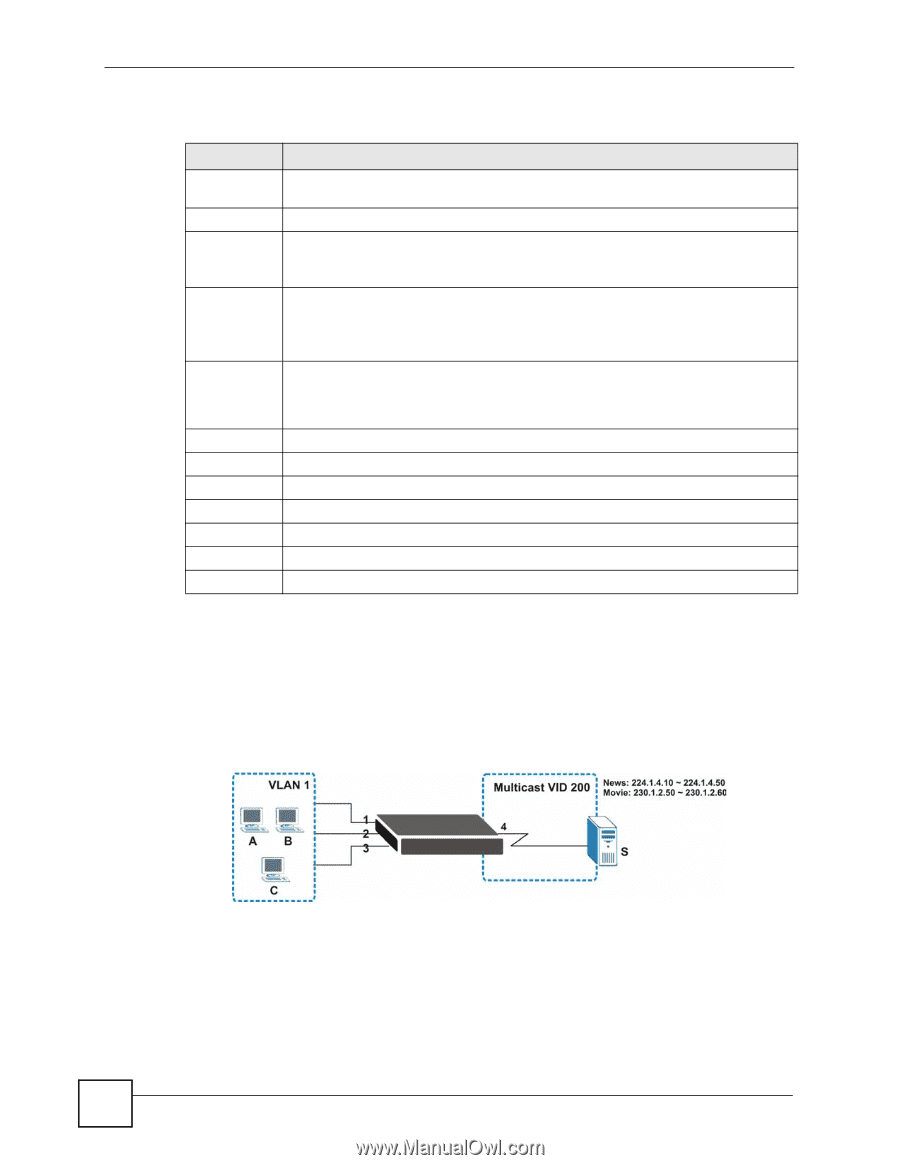
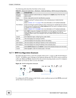
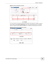
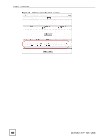
Chapter 13 Multicast The following table describes the labels in this screen. Table 25 Advanced Application > Multicast > Multicast Setting > MVR: Group Configuration LABEL DESCRIPTION Multicast VLAN ID Select a multicast VLAN ID (that you configured in the MVR screen) from the dropdown list box. Name Enter a descriptive name for identification purposes. Start Address Enter the starting IP multicast address of the multicast group in dotted decimal notation. Refer to Section 13.1.1 on page 73 for more information on IP multicast addresses. End Address Enter the ending IP multicast address of the multicast group in dotted decimal notation. Enter the same IP address as the Start Address field if you want to configure only one IP address for a multicast group. Refer to Section 13.1.1 on page 73 for more information on IP multicast addresses. Add Click Add to save your changes to the Switch's run-time memory. The Switch loses these changes if it is turned off or loses power, so use the Save link on the top navigation panel to save your changes to the non-volatile memory when you are done configuring. Cancel Click Cancel to begin configuring this screen afresh. MVLAN This field displays the multicast VLAN ID. Name This field displays the descriptive name for this setting. Start Address This field displays the starting IP address of the multicast group. End Address This field displays the ending IP address of the multicast group. Delete Select Delete Group and click Delete to remove the selected entry(ies) from the table. Cancel Select Cancel to clear the checkbox(es) in the table. 13.7.1 MVR Configuration Example The following figure shows a network example where ports 1, 2 and 3 on the Switch belong to VLAN 1. In addition, port 4 belongs to the multicast group with VID 200 to receive multicast traffic (the News and Movie channels) from the remote streaming media server, S. Computers A, B and C in VLAN are able to receive the traffic. Figure 38 MVR Configuration Example To configure the MVR settings on the Switch, create a multicast group in the MVR screen and set the receiver and source ports. 82 ES-315/ES-315-F User's Guide
-
 1
1 -
2
-
3
-
4
-
5
-
6
-
7
-
8
-
9
-
10
-
11
-
12
-
13
-
14
-
15
-
16
-
17
-
18
-
19
-
20
-
21
-
22
-
23
-
24
-
25
-
26
-
27
-
28
-
29
-
30
-
31
-
32
-
33
-
34
-
35
-
36
-
37
-
38
-
39
-
40
-
41
-
42
-
43
-
44
-
45
-
46
-
47
-
48
-
49
-
50
-
51
-
52
-
53
-
54
-
55
-
56
-
57
-
58
-
59
-
60
-
61
-
62
-
63
-
64
-
65
-
66
-
67
-
68
-
69
-
70
-
71
-
72
-
73
-
74
-
75
-
76
-
 77
77 -
 78
78 -
 79
79 -
 80
80 -
 81
81 -
 82
82 -
 83
83 -
 84
84 -
 85
85 -
 86
86 -
 87
87 -
88
-
89
-
90
-
91
-
92
-
93
-
94
-
95
-
96
-
97
-
98
-
99
-
100
-
101
-
102
-
103
-
104
-
105
-
106
-
107
-
108
-
109
-
110
-
111
-
112
-
113
-
114
-
115
-
116
-
117
-
118
-
119
-
120
-
121
-
122
-
123
-
124
-
125
-
126
-
127
-
128
-
129
-
130
-
131
-
132
-
133
-
134
-
135
-
136
-
137
-
138
-
139
-
140
-
141
-
142
-
143
-
144
-
145
-
146
-
147
-
148
-
149
-
150
-
151
-
152
-
153
-
154
-
155
-
156
-
157
-
158
-
159
-
160
-
161
-
162
-
163
-
164
-
165
-
166
 |
 |