ZyXEL ES-315 User Guide - Page 17

List of s

Page 17 highlights

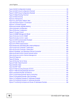
List of Figures List of Figures Figure 1 Internet Access through the Switch 23 Figure 2 Shared Server Using VLAN Example 24 Figure 3 Front Panel: ES-315 ...27 Figure 4 Front Panel: ES-315-F ...27 Figure 5 Rear Panel: ES-315 ...28 Figure 6 Rear Panel: ES-315-F ...28 Figure 7 Base Panel: ES-315-F ...29 Figure 8 Web Configurator: Login ...34 Figure 9 Web Configurator Home Screen (Status 34 Figure 10 Change Administrator Login Password 37 Figure 11 Web Configurator: Logout Screen 38 Figure 12 Initial Setup Network Example: VLAN 39 Figure 13 Initial Setup Network Example: Port VID 41 Figure 14 Initial Setup Example: Management IP Address 41 Figure 15 Status ...43 Figure 16 Status > Port Details ...44 Figure 17 System Info ...47 Figure 18 Basic Setting > General Setup 48 Figure 19 Basic Setting > Switch Setup 50 Figure 20 Basic Setting > IP Setup ...51 Figure 21 Basic Setting > Port Setup ...53 Figure 22 Advanced Application > VLAN: VLAN Status 58 Figure 23 Advanced Application > VLAN > VLAN Detail 59 Figure 24 Advanced Application > VLAN > Static VLAN 60 Figure 25 Advanced Application > VLAN > VLAN Port Setting 61 Figure 26 Advanced Application > Static MAC Forwarding 63 Figure 27 Advanced Application > Filtering 65 Figure 28 Advanced Application > Broadcast Storm Control 67 Figure 29 Advanced Application > Bandwidth Control 69 Figure 30 Queuing Method ...72 Figure 31 Advanced Application > Multicast 74 Figure 32 Advanced Application > Multicast > Multicast Setting 75 Figure 33 Advanced Application > Multicast > Multicast Setting > IGMP Filtering Profile 77 Figure 34 MVR Network Example ...78 Figure 35 MVR Multicast Television Example 79 Figure 36 Advanced Application > Multicast > Multicast Setting > MVR 80 Figure 37 Advanced Application > Multicast > Multicast Setting > MVR: Group Configuration 81 Figure 38 MVR Configuration Example 82 ES-315/ES-315-F User's Guide 17

  • 1
  • 2
  • 3
  • 4
  • 5
  • 6
  • 7
  • 8
  • 9
  • 10
  • 11
  • 12
  • 13
  • 14
  • 15
  • 16
  • 17
  • 18
  • 19
  • 20
  • 21
  • 22
  • 23
  • 24
  • 25
  • 26
  • 27
  • 28
  • 29
  • 30
  • 31
  • 32
  • 33
  • 34
  • 35
  • 36
  • 37
  • 38
  • 39
  • 40
  • 41
  • 42
  • 43
  • 44
  • 45
  • 46
  • 47
  • 48
  • 49
  • 50
  • 51
  • 52
  • 53
  • 54
  • 55
  • 56
  • 57
  • 58
  • 59
  • 60
  • 61
  • 62
  • 63
  • 64
  • 65
  • 66
  • 67
  • 68
  • 69
  • 70
  • 71
  • 72
  • 73
  • 74
  • 75
  • 76
  • 77
  • 78
  • 79
  • 80
  • 81
  • 82
  • 83
  • 84
  • 85
  • 86
  • 87
  • 88
  • 89
  • 90
  • 91
  • 92
  • 93
  • 94
  • 95
  • 96
  • 97
  • 98
  • 99
  • 100
  • 101
  • 102
  • 103
  • 104
  • 105
  • 106
  • 107
  • 108
  • 109
  • 110
  • 111
  • 112
  • 113
  • 114
  • 115
  • 116
  • 117
  • 118
  • 119
  • 120
  • 121
  • 122
  • 123
  • 124
  • 125
  • 126
  • 127
  • 128
  • 129
  • 130
  • 131
  • 132
  • 133
  • 134
  • 135
  • 136
  • 137
  • 138
  • 139
  • 140
  • 141
  • 142
  • 143
  • 144
  • 145
  • 146
  • 147
  • 148
  • 149
  • 150
  • 151
  • 152
  • 153
  • 154
  • 155
  • 156
  • 157
  • 158
  • 159
  • 160
  • 161
  • 162
  • 163
  • 164
  • 165
  • 166

List of Figures
ES-315/ES-315-F User’s Guide
17
List of Figures
Figure 1 Internet Access through the Switch
..........................................................................................
23
Figure 2 Shared Server Using VLAN Example
......................................................................................
24
Figure 3 Front Panel: ES-315
................................................................................................................
27
Figure 4 Front Panel: ES-315-F
............................................................................................................
27
Figure 5 Rear Panel: ES-315
................................................................................................................
28
Figure 6 Rear Panel: ES-315-F
.............................................................................................................
28
Figure 7 Base Panel: ES-315-F
.............................................................................................................
29
Figure 8 Web Configurator: Login
.........................................................................................................
34
Figure 9 Web Configurator Home Screen (Status)
................................................................................
34
Figure 10 Change Administrator Login Password
.................................................................................
37
Figure 11 Web Configurator: Logout Screen
.........................................................................................
38
Figure 12 Initial Setup Network Example: VLAN
...................................................................................
39
Figure 13 Initial Setup Network Example: Port VID
...............................................................................
41
Figure 14 Initial Setup Example: Management IP Address
...................................................................
41
Figure 15 Status
....................................................................................................................................
43
Figure 16 Status > Port Details
..............................................................................................................
44
Figure 17 System Info
...........................................................................................................................
47
Figure 18 Basic Setting > General Setup
..............................................................................................
48
Figure 19 Basic Setting > Switch Setup
................................................................................................
50
Figure 20 Basic Setting > IP Setup
.........................................................................................................
51
Figure 21 Basic Setting > Port Setup
....................................................................................................
53
Figure 22 Advanced Application > VLAN: VLAN Status
........................................................................
58
Figure 23 Advanced Application > VLAN > VLAN Detail
........................................................................
59
Figure 24 Advanced Application > VLAN > Static VLAN
......................................................................
60
Figure 25 Advanced Application > VLAN > VLAN Port Setting
.............................................................
61
Figure 26 Advanced Application > Static MAC Forwarding
...................................................................
63
Figure 27 Advanced Application > Filtering
...........................................................................................
65
Figure 28 Advanced Application > Broadcast Storm Control
................................................................
67
Figure 29 Advanced Application > Bandwidth Control
..........................................................................
69
Figure 30 Queuing Method
....................................................................................................................
72
Figure 31 Advanced Application > Multicast
..........................................................................................
74
Figure 32 Advanced Application > Multicast > Multicast Setting
...........................................................
75
Figure 33 Advanced Application > Multicast > Multicast Setting > IGMP Filtering Profile
.....................
77
Figure 34 MVR Network Example
.........................................................................................................
78
Figure 35 MVR Multicast Television Example
.......................................................................................
79
Figure 36 Advanced Application > Multicast > Multicast Setting > MVR
...............................................
80
Figure 37 Advanced Application > Multicast > Multicast Setting > MVR: Group Configuration
..............
81
Figure 38 MVR Configuration Example
.................................................................................................
82