ZyXEL P-128 User Guide - Page 37
Hardware Installation & Initial Setup
 |
View all ZyXEL P-128 manuals
Add to My Manuals
Save this manual to your list of manuals |
Page 37 highlights
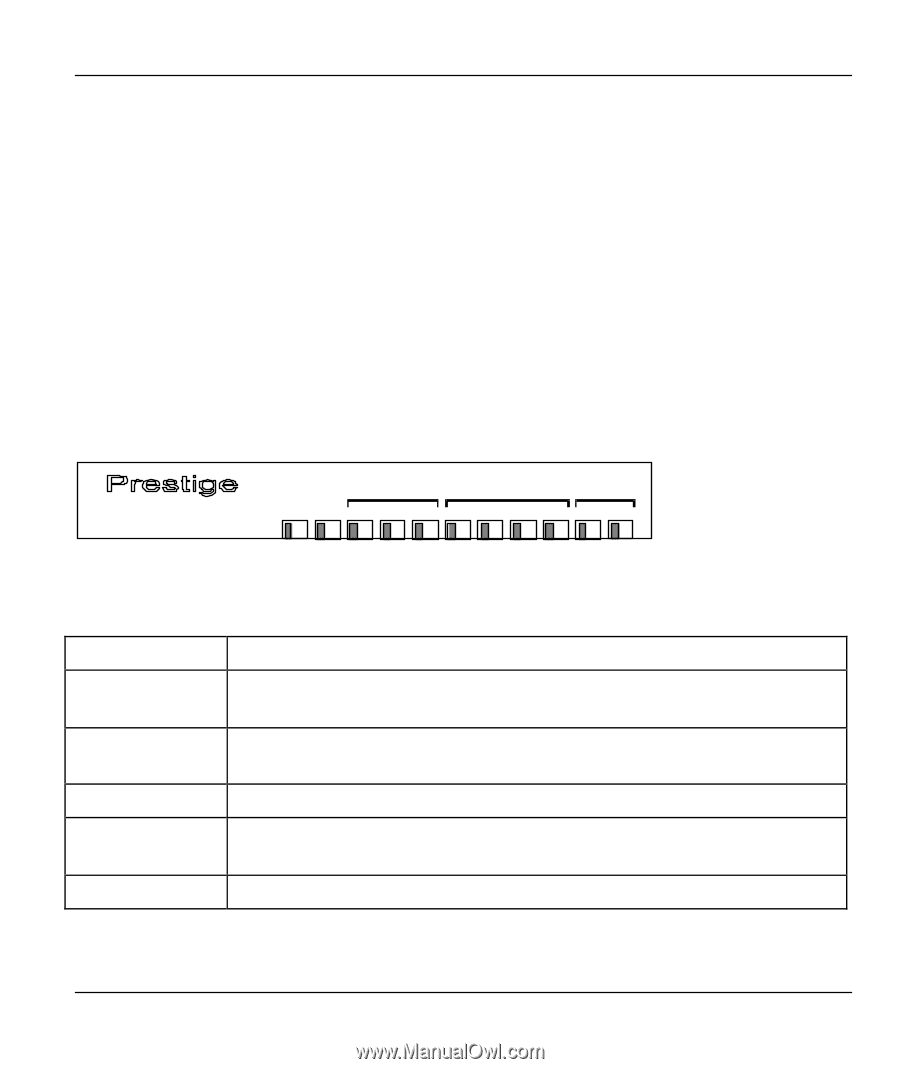
Prestige 128IMH ISDN Modem/ Router/Hub Chapter 2 Hardware Installation & Initial Setup This chapter shows you how to connect the hardware and the initial setup. 2.1.1 Front Panel LEDS The LED indicators on the front panel indicate the router/hub functional status of the Prestige. The following table describes the LED functions: Remote Access Router ISDN LAN PHONE PWR TST LNK B1 B2 1 2 3 4 1 2 Figure 2-1 Front Panel PWR TST ISDN: LNK ISDN: B1/B2 LAN: 1 to 4 PHONE: 1/2 The PWR (power) LED is on when power is applied to the Prestige. A blinking TST (test) LED indicates the Prestige is functioning properly. A steady or an off TST indicates malfunction. The LNK (Link) LED is on when the Prestige is connected to an ISDN switch and the line has been successfully initialized. The B1/B2 LED is on when the corresponding B channel is in use. A steady LED indicates an active station is connected to the corresponding port. The LED blinks when the connected station is transmitting. The LED is on when the device on the corresponding POTS port is in use. Table 2-1 LED functions Hardware Installation and Setup 2-1
-
 1
1 -
2
-
3
-
4
-
5
-
6
-
7
-
8
-
9
-
10
-
11
-
12
-
13
-
14
-
15
-
16
-
17
-
18
-
19
-
20
-
21
-
22
-
23
-
24
-
25
-
26
-
27
-
28
-
29
-
30
-
31
-
 32
32 -
 33
33 -
 34
34 -
 35
35 -
 36
36 -
 37
37 -
 38
38 -
 39
39 -
 40
40 -
 41
41 -
 42
42 -
43
-
44
-
45
-
46
-
47
-
48
-
49
-
50
-
51
-
52
-
53
-
54
-
55
-
56
-
57
-
58
-
59
-
60
-
61
-
62
-
63
-
64
-
65
-
66
-
67
-
68
-
69
-
70
-
71
-
72
-
73
-
74
-
75
-
76
-
77
-
78
-
79
-
80
-
81
-
82
-
83
-
84
-
85
-
86
-
87
-
88
-
89
-
90
-
91
-
92
-
93
-
94
-
95
-
96
-
97
-
98
-
99
-
100
-
101
-
102
-
103
-
104
-
105
-
106
-
107
-
108
-
109
-
110
-
111
-
112
-
113
-
114
-
115
-
116
-
117
-
118
-
119
-
120
-
121
-
122
-
123
-
124
-
125
-
126
-
127
-
128
-
129
-
130
-
131
-
132
-
133
-
134
-
135
-
136
-
137
-
138
-
139
-
140
-
141
-
142
-
143
-
144
-
145
-
146
-
147
-
148
-
149
-
150
-
151
-
152
-
153
-
154
-
155
-
156
-
157
-
158
-
159
-
160
-
161
-
162
-
163
-
164
-
165
-
166
-
167
-
168
-
169
-
170
-
171
-
172
-
173
-
174
-
175
-
176
-
177
-
178
-
179
-
180
-
181
-
182
-
183
-
184
-
185
-
186
-
187
-
188
-
189
-
190
-
191
 |
 |