Brother International S-7200B Service Manual - Page 25
FUNCTION SETTINGS OPERATION PANEL, Function No. 108, <Stitch number control output signal>
 |
View all Brother International S-7200B manuals
Add to My Manuals
Save this manual to your list of manuals |
Page 25 highlights
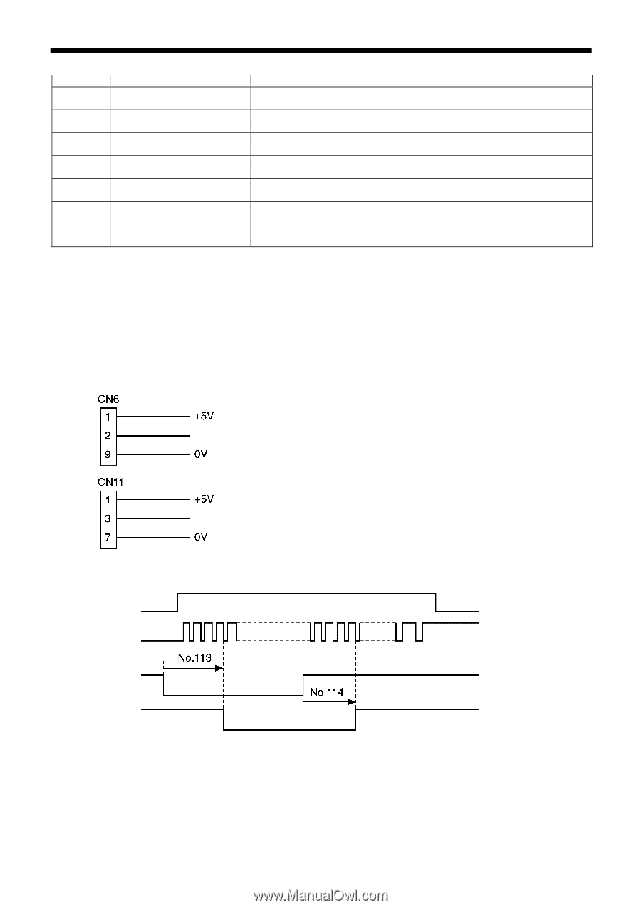
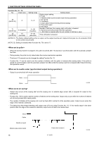
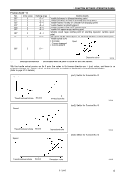
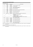
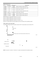
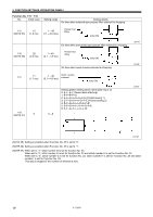
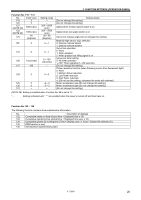
3. FUNCTION SETTINGS (OPERATION PANEL) Function No. 108 − 114 No. Initial value 108 (NOTE 30) 0 (needles) 109 (NOTE 31) 10 (ms) 110 (NOTE 31) 0 (ms) 111 (NOTE 32) 0 (ms) 112 (NOTE 33) 2000 (ms) 113 (NOTE 34) 0 (needles) 114 (NOTE 34) 0 (needles) Setting range 0 - 99 (needles) 0 - 990 (ms) Setting details Number of stitches for option output (C1) Delay time until option output turns on (C2) 0 - 990 (ms) Option output on time (C3) 0 - 990 (ms) Delay time until option output turns on (C4) 0 - 9900 (ms) 0 - 99 (needles) 0 - 99 (needles) Option output on time (C5) Number of stitches for option output (C6) Number of stitches for option output (C7) (NOTE 30) Setting is enabled when Function No. 70 is set to "2". (NOTE 31) Setting is enabled when Function No. 70 is set to "4". (NOTE 32) Setting is enabled when Function No. 70 is set to "5". (NOTE 33) Setting is enabled when Function No. 70 is set to "2" or "5". (NOTE 34) The stitch number control output signal can be set in accordance with the variable input signal. The variable input signal should be connected to connector CN6. The output signal is sent to connector CN11. External input External output; signal is open collector output within maximum 10 mA 2262M Motor Needle up signal Variable input signal Output signal NOTE: If Function No. 112 and No. 113 are set to "0", output is synchronized with the variable input signal. 2263M S-7200B 18
-
 1
1 -
2
-
3
-
4
-
5
-
6
-
7
-
8
-
9
-
10
-
11
-
12
-
13
-
14
-
15
-
16
-
17
-
18
-
19
-
 20
20 -
 21
21 -
 22
22 -
 23
23 -
 24
24 -
 25
25 -
 26
26 -
 27
27 -
 28
28 -
 29
29 -
 30
30 -
31
-
32
-
33
-
34
-
35
-
36
-
37
-
38
-
39
-
40
-
41
-
42
-
43
-
44
-
45
-
46
-
47
-
48
-
49
-
50
-
51
-
52
-
53
-
54
-
55
-
56
-
57
-
58
-
59
-
60
-
61
-
62
-
63
-
64
-
65
-
66
-
67
-
68
-
69
-
70
-
71
-
72
-
73
-
74
-
75
-
76
-
77
-
78
-
79
-
80
-
81
-
82
-
83
-
84
 |
 |