Brother International S-7200B Service Manual - Page 38
Adjusting the needle and rotary hook timing, ADJUSTMENTS
 |
View all Brother International S-7200B manuals
Add to My Manuals
Save this manual to your list of manuals |
Page 38 highlights
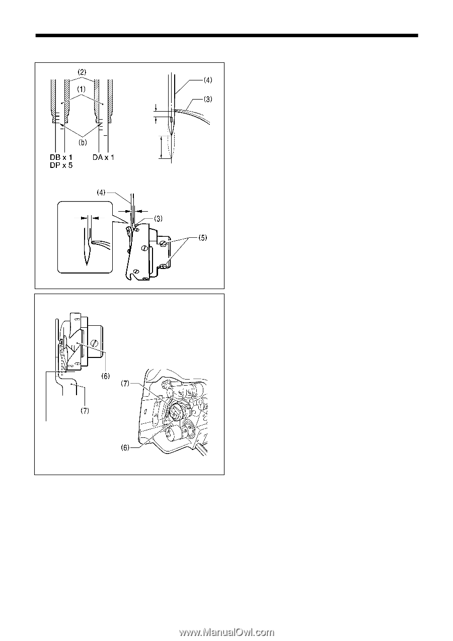
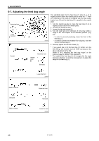
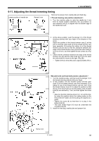
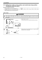
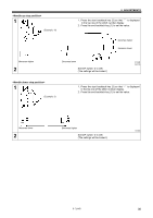
6. ADJUSTMENTS 6-10. Adjusting the needle and rotary hook timing 2290M 0.5 - 0.7mm 1.8mm 2.2mm 0 - 0.05mm 0.05mm 2291M The tip of the rotary hook (3) should be aligned with the center of the needle (4) when the needle bar (1) moves up from its lowest position to the position where reference line (b), which is the line at the bottom of the needle bar (1)(third line from the bottom when using a DA x 1 needle), is aligned with the lower edge of the needle bar bush D (2) as shown in the illustration. (At this time, the gap between the upper edge of the needle hole and the rotary hook tip (3) will be 0.5 - 0.7 mm.) 1. Turn the machine pulley to raise the needle bar (1) from its lowest position until reference line (b) is aligned with the lower edge of the needle bar bush D (2) as shown in the illustration. (The needle should rise by 1.8 mm [2.2 mm for -[][]5 specifications] and the distance from the needle hole to the tip of the rotary hook should be 0.5 - 0.7 mm.) 2. Loosen the three set screws (5), and then align the tip of the rotary hook (3) with the center of the needle (4). The distance between the tip of the rotary hook (3) and the needle (4) should be approximately 0 - 0.05 mm. 3. Securely tighten the three set screws (5). 2292M Check that the clearance between the rotary hook (6) and the bobbin case holder position bracket (7) is enough to allow the thread being used to pass through smoothly. The clearance should be 0.4 - 0.7 mm for -[][]S / [][]3 models, and 0.6 - 1.1 mm for -[][]5 models. 0.4 - 0.7mm 0.6 - 1.1mm 2293M 3700M 31 S-7200B
-
 1
1 -
2
-
3
-
4
-
5
-
6
-
7
-
8
-
9
-
10
-
11
-
12
-
13
-
14
-
15
-
16
-
17
-
18
-
19
-
20
-
21
-
22
-
23
-
24
-
25
-
26
-
27
-
28
-
29
-
30
-
31
-
32
-
 33
33 -
 34
34 -
 35
35 -
 36
36 -
 37
37 -
 38
38 -
 39
39 -
 40
40 -
 41
41 -
 42
42 -
 43
43 -
44
-
45
-
46
-
47
-
48
-
49
-
50
-
51
-
52
-
53
-
54
-
55
-
56
-
57
-
58
-
59
-
60
-
61
-
62
-
63
-
64
-
65
-
66
-
67
-
68
-
69
-
70
-
71
-
72
-
73
-
74
-
75
-
76
-
77
-
78
-
79
-
80
-
81
-
82
-
83
-
84
 |
 |