Brother International S-7200B Service Manual - Page 64
Standard setting values, Treadle unit H
 |
View all Brother International S-7200B manuals
Add to My Manuals
Save this manual to your list of manuals |
Page 64 highlights
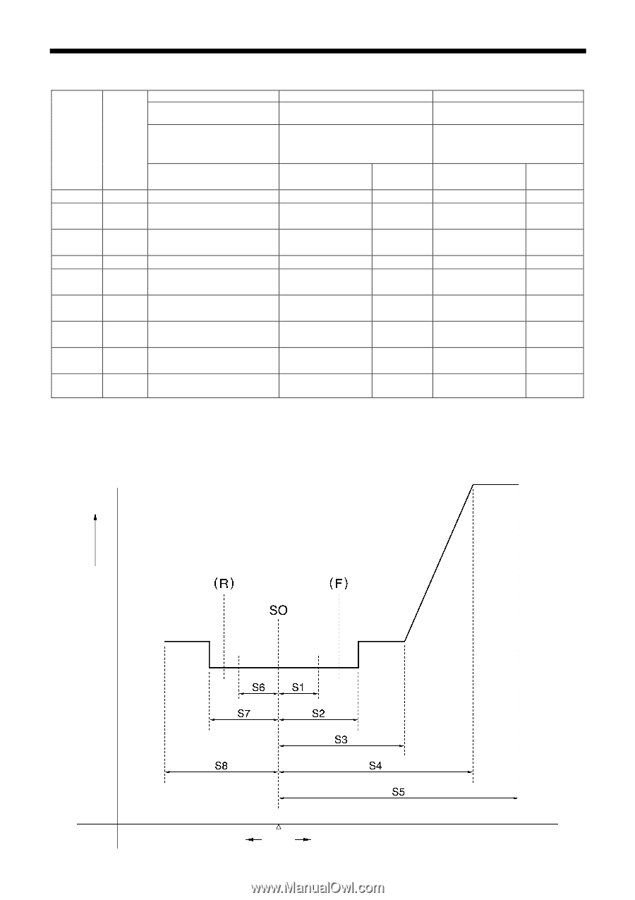
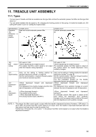
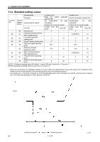
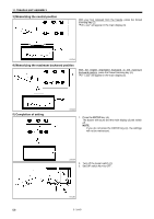
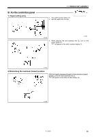
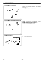
11. TREADLE UNIT ASSEMBLY 11-2. Standard setting values Function No. Symbol (diagram below) Specifications Operation Spring position setting Treadle unit G Does not control automatic presser lifter No forward/back 1st step modulation (Figure [a] on previous page) Treadle unit H Controls automatic presser lifter Forward/back 1st step modulation (Figure [b] on previous page) Function Length (mm) from S0 Force (N) Length from S0 (mm) Force (N) - S0 Neutral point 0 - 0 - 82 S1 Forward automatic presser - lifter operating point - 2 (NOTE 1) 10 83 S2 Low speed operation starting point 3 10 5 25 84 S3 Speed change starting point 6 - 7 - 85 S4 Maximum speed reaching S5-1 - S5-1 - point - S5 Maximum forward depression point 14.5 12 14.5 32 81 S6 Back automatic presser - lifter operating point 80 S7 Thread trimmer operating 5 point - S8 Maximum back depression point 8 - 2 (NOTE 2) 14 22 5 35 28 8 43 (NOTE 1) Setting is enabled when DIP switch 1 is set to ON and Function No. 13 is set to "1". (NOTE 2) Setting is enabled when Function No. 12 is set to "0". ・ When the connecting rod installation position is on the inside, the measurement value is the amount of movement of the treadle from the neutral position to the forward position and to the backward position. ・ For treadle unit -H, the point of change (F) in the forward depression force is between S1 and S2, and the point of change (R) in the backward depression force is between S6 and S7. Speed Backward depression Neutral Forward depression 57 S-7200B 1841M
-
 1
1 -
2
-
3
-
4
-
5
-
6
-
7
-
8
-
9
-
10
-
11
-
12
-
13
-
14
-
15
-
16
-
17
-
18
-
19
-
20
-
21
-
22
-
23
-
24
-
25
-
26
-
27
-
28
-
29
-
30
-
31
-
32
-
33
-
34
-
35
-
36
-
37
-
38
-
39
-
40
-
41
-
42
-
43
-
44
-
45
-
46
-
47
-
48
-
49
-
50
-
51
-
52
-
53
-
54
-
55
-
56
-
57
-
58
-
 59
59 -
 60
60 -
 61
61 -
 62
62 -
 63
63 -
 64
64 -
 65
65 -
 66
66 -
 67
67 -
 68
68 -
 69
69 -
70
-
71
-
72
-
73
-
74
-
75
-
76
-
77
-
78
-
79
-
80
-
81
-
82
-
83
-
84
 |
 |