Cisco 6509 Installation Guide - Page 126
Establishing the System Ground
 |
UPC - 746320196077
View all Cisco 6509 manuals
Add to My Manuals
Save this manual to your list of manuals |
Page 126 highlights
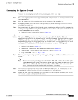
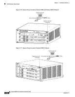
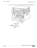
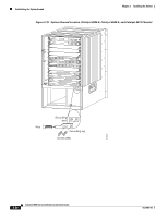
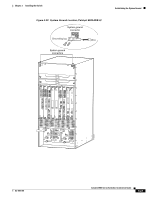
Establishing the System Ground Chapter 3 Installing the Switch Establishing the System Ground This section describes how to connect a system ground to the Catalyst 6500 series switches. Note This system ground is also referred to as the network equipment building system (NEBS) ground. You must use the system (NEBS) ground on both AC- and DC-powered systems if you are installing Foreign Exchange Station (FXS) modules or if you are installing this equipment in a U.S. or European Central Office. The system (NEBS) ground provides additional grounding for EMI shielding requirements and grounding for the low voltage supplies (DC-DC converters) on the modules and is intended to satisfy the Telcordia Technologies NEBS requirements for supplemental bonding and grounding connections. You must observe the following system grounding guidelines for your chassis: • You must install the system (NEBS) ground connection with any other rack or system power ground connections that you make. The system ground connection is required if FXS modules are installed or if this equipment is installed in a U.S. or European Central Office. • You must connect both the system (NEBS) ground connection and the power supply ground connection to an earth ground. The system (NEBS) ground connection is required if FXS modules are installed or if this equipment is installed in a U.S. or European Central Office. • For Catalyst 6503 or Catalyst 6503-E chassis that are equipped with DC-input power supplies, you must install the system (NEBS) ground before you attach the source DC power cables to the DC PEM. If the Catalyst 6503 or Catalyst 6503-E chassis is powered up, you must power down the chassis before attaching the system (NEBS) ground. If you are installing the system (NEBS) ground on other models of the Catalyst 6500 series chassis that are equipped with either AC-input or DC-input power supplies, you do not need to power down the chassis. Note The system (NEBS) ground serves as the primary safety ground for the Catalyst 6503 and Catalyst 6503-E chassis that are equipped with DC-input power supplies. The DC-input power supplies for these chassis do not have a separate ground. Required Tools and Equipment To connect the system ground, you need the following tools and materials: • Grounding lug-A two holes standard barrel lug. Supports up to 6 AWG wire. Supplied as part of accessory kit. • Grounding screws-Two M4 x 8mm (metric) pan-head screws. Supplied as part of the accessory kit. • Grounding wire-Not supplied as part of accessory kit. The grounding wire should be sized according to local and national installation requirements. Depending on the power supply and system, a 12 AWG to 6 AWG copper conductor is required for U.S. installations. Commercially available 6 AWG wire is recommended. The length of the grounding wire depends on the proximity of the switch to proper grounding facilities. • No. 1 Phillips screwdriver. • Crimping tool to crimp the grounding wire to the grounding lug. • Wire-stripping tool to remove the insulation from the grounding wire. 3-22 Catalyst 6500 Series Switches Installation Guide OL-5781-04
-
 1
1 -
2
-
3
-
4
-
5
-
6
-
7
-
8
-
9
-
10
-
11
-
12
-
13
-
14
-
15
-
16
-
17
-
18
-
19
-
20
-
21
-
22
-
23
-
24
-
25
-
26
-
27
-
28
-
29
-
30
-
31
-
32
-
33
-
34
-
35
-
36
-
37
-
38
-
39
-
40
-
41
-
42
-
43
-
44
-
45
-
46
-
47
-
48
-
49
-
50
-
51
-
52
-
53
-
54
-
55
-
56
-
57
-
58
-
59
-
60
-
61
-
62
-
63
-
64
-
65
-
66
-
67
-
68
-
69
-
70
-
71
-
72
-
73
-
74
-
75
-
76
-
77
-
78
-
79
-
80
-
81
-
82
-
83
-
84
-
85
-
86
-
87
-
88
-
89
-
90
-
91
-
92
-
93
-
94
-
95
-
96
-
97
-
98
-
99
-
100
-
101
-
102
-
103
-
104
-
105
-
106
-
107
-
108
-
109
-
110
-
111
-
112
-
113
-
114
-
115
-
116
-
117
-
118
-
119
-
120
-
 121
121 -
 122
122 -
 123
123 -
 124
124 -
 125
125 -
 126
126 -
 127
127 -
 128
128 -
 129
129 -
 130
130 -
 131
131 -
132
-
133
-
134
-
135
-
136
-
137
-
138
-
139
-
140
-
141
-
142
-
143
-
144
-
145
-
146
-
147
-
148
-
149
-
150
-
151
-
152
-
153
-
154
-
155
-
156
-
157
-
158
-
159
-
160
-
161
-
162
-
163
-
164
-
165
-
166
-
167
-
168
-
169
-
170
-
171
-
172
-
173
-
174
-
175
-
176
-
177
-
178
-
179
-
180
-
181
-
182
-
183
-
184
-
185
-
186
-
187
-
188
-
189
-
190
-
191
-
192
-
193
-
194
-
195
-
196
-
197
-
198
-
199
-
200
-
201
-
202
-
203
-
204
-
205
-
206
-
207
-
208
-
209
-
210
-
211
-
212
-
213
-
214
-
215
-
216
-
217
-
218
-
219
-
220
-
221
-
222
-
223
-
224
-
225
-
226
-
227
-
228
-
229
-
230
-
231
-
232
-
233
-
234
-
235
-
236
-
237
-
238
-
239
-
240
-
241
-
242
-
243
-
244
-
245
-
246
-
247
-
248
-
249
-
250
-
251
-
252
-
253
-
254
-
255
-
256
-
257
-
258
-
259
-
260
-
261
-
262
-
263
-
264
-
265
-
266
-
267
-
268
-
269
-
270
-
271
-
272
-
273
-
274
-
275
-
276
-
277
-
278
-
279
-
280
-
281
-
282
-
283
-
284
-
285
-
286
-
287
-
288
-
289
-
290
-
291
-
292
-
293
-
294
-
295
-
296
-
297
-
298
-
299
-
300
-
301
-
302
-
303
-
304
-
305
-
306
-
307
-
308
-
309
-
310
-
311
-
312
-
313
-
314
-
315
-
316
-
317
-
318
-
319
-
320
-
321
-
322
-
323
-
324
-
325
-
326
-
327
-
328
-
329
-
330
-
331
-
332
-
333
-
334
-
335
-
336
 |
 |
