Cisco 6509 Installation Guide - Page 196
Installing the DC-Input PEM
 |
UPC - 746320196077
View all Cisco 6509 manuals
Add to My Manuals
Save this manual to your list of manuals |
Page 196 highlights
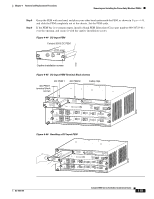
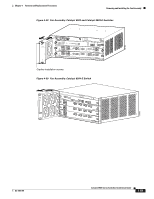
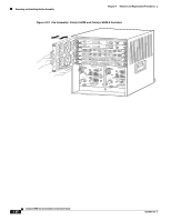
Removing and Installing the Power Entry Modules (PEMs) Chapter 4 Removal and Replacement Procedures Installing the DC-Input PEM Warning Before performing any of the following procedures, ensure that power is removed from the DC circuit. Statement 1003 Warning When installing or replacing the unit, the ground connection must always be made first and disconnected last. Statement 1046 Follow these steps to install a DC-input PEM: Step 1 Step 2 Step 3 Step 4 Step 5 Step 6 Ensure that the system (earth) ground connection has been made. For ground connection installation instructions, see the "Establishing the System Ground" section on page 3-22. Verify that power is off to the DC circuit for the PEM that you are installing. As an added precaution, place the appropriate safety flag and lockout devices at the source power circuit breaker, or place a piece of adhesive tape over the circuit breaker handle to prevent accidental power restoration while you are working on the circuit. Install the PEM part way in the chassis so that you still have access to the PEM terminal block screws. (See Figure 4-47.) Connect the DC-input wires to the terminal block in this order: 1. Negative (-) 2. Positive (+) After ensuring that all wire connections are secure, install the PEM in the bay. Tighten the power supply captive installation screws. (See Figure 4-48.) Caution In a system with dual power supplies, connect each power supply to a separate input line. In case of a line failure, the second source will most likely still be available. Step 7 Step 8 Remove the safety flag, lockout devices, or tape from the circuit breaker switch handle, and restore power by moving the circuit breaker switch handle to the On (|) position. Verify the power supply operation by ensuring that the power supply front panel LEDs are in the following states: • INPUT OK LED is green • FAN OK LED is green • OUTPUT FAIL LED is not lit If the LEDs indicate a power problem, see the "Identifying Startup Problems" section on page E-3. 4-56 Catalyst 6500 Series Switches Installation Guide OL-5781-04
-
 1
1 -
2
-
3
-
4
-
5
-
6
-
7
-
8
-
9
-
10
-
11
-
12
-
13
-
14
-
15
-
16
-
17
-
18
-
19
-
20
-
21
-
22
-
23
-
24
-
25
-
26
-
27
-
28
-
29
-
30
-
31
-
32
-
33
-
34
-
35
-
36
-
37
-
38
-
39
-
40
-
41
-
42
-
43
-
44
-
45
-
46
-
47
-
48
-
49
-
50
-
51
-
52
-
53
-
54
-
55
-
56
-
57
-
58
-
59
-
60
-
61
-
62
-
63
-
64
-
65
-
66
-
67
-
68
-
69
-
70
-
71
-
72
-
73
-
74
-
75
-
76
-
77
-
78
-
79
-
80
-
81
-
82
-
83
-
84
-
85
-
86
-
87
-
88
-
89
-
90
-
91
-
92
-
93
-
94
-
95
-
96
-
97
-
98
-
99
-
100
-
101
-
102
-
103
-
104
-
105
-
106
-
107
-
108
-
109
-
110
-
111
-
112
-
113
-
114
-
115
-
116
-
117
-
118
-
119
-
120
-
121
-
122
-
123
-
124
-
125
-
126
-
127
-
128
-
129
-
130
-
131
-
132
-
133
-
134
-
135
-
136
-
137
-
138
-
139
-
140
-
141
-
142
-
143
-
144
-
145
-
146
-
147
-
148
-
149
-
150
-
151
-
152
-
153
-
154
-
155
-
156
-
157
-
158
-
159
-
160
-
161
-
162
-
163
-
164
-
165
-
166
-
167
-
168
-
169
-
170
-
171
-
172
-
173
-
174
-
175
-
176
-
177
-
178
-
179
-
180
-
181
-
182
-
183
-
184
-
185
-
186
-
187
-
188
-
189
-
190
-
 191
191 -
 192
192 -
 193
193 -
 194
194 -
 195
195 -
 196
196 -
 197
197 -
 198
198 -
 199
199 -
 200
200 -
 201
201 -
202
-
203
-
204
-
205
-
206
-
207
-
208
-
209
-
210
-
211
-
212
-
213
-
214
-
215
-
216
-
217
-
218
-
219
-
220
-
221
-
222
-
223
-
224
-
225
-
226
-
227
-
228
-
229
-
230
-
231
-
232
-
233
-
234
-
235
-
236
-
237
-
238
-
239
-
240
-
241
-
242
-
243
-
244
-
245
-
246
-
247
-
248
-
249
-
250
-
251
-
252
-
253
-
254
-
255
-
256
-
257
-
258
-
259
-
260
-
261
-
262
-
263
-
264
-
265
-
266
-
267
-
268
-
269
-
270
-
271
-
272
-
273
-
274
-
275
-
276
-
277
-
278
-
279
-
280
-
281
-
282
-
283
-
284
-
285
-
286
-
287
-
288
-
289
-
290
-
291
-
292
-
293
-
294
-
295
-
296
-
297
-
298
-
299
-
300
-
301
-
302
-
303
-
304
-
305
-
306
-
307
-
308
-
309
-
310
-
311
-
312
-
313
-
314
-
315
-
316
-
317
-
318
-
319
-
320
-
321
-
322
-
323
-
324
-
325
-
326
-
327
-
328
-
329
-
330
-
331
-
332
-
333
-
334
-
335
-
336
 |
 |