Cisco 6509 Installation Guide - Page 135
Step 6, Step 7, Step 8, Step 9, Step 10, Step 11, Caution
 |
UPC - 746320196077
View all Cisco 6509 manuals
Add to My Manuals
Save this manual to your list of manuals |
Page 135 highlights
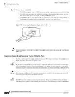
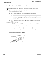
Chapter 3 Installing the Switch Attaching the Interface Cables Step 6 Insert the GBIC transceiver into the socket until you feel the GBIC transceiver module connector snap into place in the socket connector. Note For optical GBIC transceivers, before removing the dust plugs and making any optical connections, observe the following guidelines: • Always keep the protective dust plugs on the unplugged fiber-optic cable connectors and the transceiver optical bores until you are ready to make a connection. • Always inspect and clean the SC connector end-faces just before making any connections. (See the Tip on this page for a pointer to more information about fiber-optic inspection and cleaning.) • Always grasp the SC connector housing to plug or unplug a fiber-optic cable. Step 7 Step 8 Remove the dust plugs from the network interface cable SC connectors. Save the dust plugs for future use. Inspect and clean the fiber-optic end-faces on the SC connector. (See the Tip below for a pointer to more information about fiber-optic inspection and cleaning.) Tip For complete information on inspecting and cleaning fiber-optic connections, refer to the document at this URL: http://www.cisco.com/en/US/tech/tk482/tk607/technologies_white_paper09186a0080254eba.shtml Step 9 Step 10 Step 11 Remove the dust plugs from the GBIC transceiver optical bores. Immediately attach the network interface cable SC connector to the GBIC transceiver. To connect 1000BASE-T GBIC transceivers to a copper network, perform the following substeps: Caution To comply with GR-1089 intrabuilding lightning immunity requirements, you must use grounded, shielded, twisted-pair, Category 5 cabling. a. Insert the Category 5 network cable RJ-45 connector into the GBIC transceiver. Note When connecting to a 1000BASE-T-compatible server, workstation, or router, use four twisted-pair, straight-through Category 5 cabling for the GBIC transceiver port. When connecting to a 1000BASE-T-compatible switch or repeater, use four twisted-pair, crossover Category 5 cabling. b. Insert the other end of the network cable into an RJ-45 port on a 1000BASE-T-compatible target device. OL-5781-04 Catalyst 6500 Series Switches Installation Guide 3-31
-
 1
1 -
2
-
3
-
4
-
5
-
6
-
7
-
8
-
9
-
10
-
11
-
12
-
13
-
14
-
15
-
16
-
17
-
18
-
19
-
20
-
21
-
22
-
23
-
24
-
25
-
26
-
27
-
28
-
29
-
30
-
31
-
32
-
33
-
34
-
35
-
36
-
37
-
38
-
39
-
40
-
41
-
42
-
43
-
44
-
45
-
46
-
47
-
48
-
49
-
50
-
51
-
52
-
53
-
54
-
55
-
56
-
57
-
58
-
59
-
60
-
61
-
62
-
63
-
64
-
65
-
66
-
67
-
68
-
69
-
70
-
71
-
72
-
73
-
74
-
75
-
76
-
77
-
78
-
79
-
80
-
81
-
82
-
83
-
84
-
85
-
86
-
87
-
88
-
89
-
90
-
91
-
92
-
93
-
94
-
95
-
96
-
97
-
98
-
99
-
100
-
101
-
102
-
103
-
104
-
105
-
106
-
107
-
108
-
109
-
110
-
111
-
112
-
113
-
114
-
115
-
116
-
117
-
118
-
119
-
120
-
121
-
122
-
123
-
124
-
125
-
126
-
127
-
128
-
129
-
 130
130 -
 131
131 -
 132
132 -
 133
133 -
 134
134 -
 135
135 -
 136
136 -
 137
137 -
 138
138 -
 139
139 -
 140
140 -
141
-
142
-
143
-
144
-
145
-
146
-
147
-
148
-
149
-
150
-
151
-
152
-
153
-
154
-
155
-
156
-
157
-
158
-
159
-
160
-
161
-
162
-
163
-
164
-
165
-
166
-
167
-
168
-
169
-
170
-
171
-
172
-
173
-
174
-
175
-
176
-
177
-
178
-
179
-
180
-
181
-
182
-
183
-
184
-
185
-
186
-
187
-
188
-
189
-
190
-
191
-
192
-
193
-
194
-
195
-
196
-
197
-
198
-
199
-
200
-
201
-
202
-
203
-
204
-
205
-
206
-
207
-
208
-
209
-
210
-
211
-
212
-
213
-
214
-
215
-
216
-
217
-
218
-
219
-
220
-
221
-
222
-
223
-
224
-
225
-
226
-
227
-
228
-
229
-
230
-
231
-
232
-
233
-
234
-
235
-
236
-
237
-
238
-
239
-
240
-
241
-
242
-
243
-
244
-
245
-
246
-
247
-
248
-
249
-
250
-
251
-
252
-
253
-
254
-
255
-
256
-
257
-
258
-
259
-
260
-
261
-
262
-
263
-
264
-
265
-
266
-
267
-
268
-
269
-
270
-
271
-
272
-
273
-
274
-
275
-
276
-
277
-
278
-
279
-
280
-
281
-
282
-
283
-
284
-
285
-
286
-
287
-
288
-
289
-
290
-
291
-
292
-
293
-
294
-
295
-
296
-
297
-
298
-
299
-
300
-
301
-
302
-
303
-
304
-
305
-
306
-
307
-
308
-
309
-
310
-
311
-
312
-
313
-
314
-
315
-
316
-
317
-
318
-
319
-
320
-
321
-
322
-
323
-
324
-
325
-
326
-
327
-
328
-
329
-
330
-
331
-
332
-
333
-
334
-
335
-
336
 |
 |