| Section |
Page |
| Catalyst 6500 Series Switches Installation Guide |
1 |
| Preface�����xi |
5 |
| chapter 1 |
5 |
| Product Overview�����1-1 |
5 |
| chapter 2 |
6 |
| Preparing for Installation�����2-1 |
6 |
| chapter 3 |
6 |
| Installing the Switch�����3-1 |
6 |
| chapter 4 |
7 |
| Removal and Replacement Procedures�����4-1 |
7 |
| appendix A |
8 |
| Power Supply Specifications�����A-1 |
8 |
| appendix B |
8 |
| Transceivers, Module Connectors, and Cable Specifications�����B-1 |
8 |
| appendix C |
9 |
| Repacking the�Switch�����C-1 |
9 |
| appendix D |
9 |
| Chassis and Module Power and Heat Values�����D-1 |
9 |
| appendix E |
9 |
| Troubleshooting�����E-1 |
9 |
| Index |
9 |
| Preface |
11 |
| Audience |
11 |
| Organization |
11 |
| Conventions |
12 |
| Statement 1071—Warning Definition |
14 |
| Related Documentation |
19 |
| Obtaining Documentation |
20 |
| Cisco.com |
20 |
| Documentation DVD |
20 |
| Ordering Documentation |
20 |
| Documentation Feedback |
21 |
| Cisco Product Security Overview |
21 |
| Reporting Security Problems in Cisco Products |
21 |
| Obtaining Technical Assistance |
22 |
| Cisco Technical Support Website |
22 |
| Submitting a Service Request |
22 |
| Definitions of Service Request Severity |
23 |
| Obtaining Additional Publications and Information |
23 |
| 1 |
25 |
| Product Overview |
25 |
| Catalyst 6503 Switch |
26 |
| Table�1-1 Catalyst 6503 Switch Features� |
26 |
| Table�1-2 Catalyst 6503 Switch Specifications� |
29 |
| Figure�1-1 Catalyst 6503 Switch—Front View |
30 |
| Figure�1-2 Catalyst 6503 Switch—Rear View |
31 |
| Catalyst 6503-E Switch |
32 |
| Table�1-3 Catalyst 6503-E Switch Features� |
32 |
| Table�1-4 Catalyst 6503-E Switch Specifications� |
34 |
| Figure�1-3 Catalyst 6503-E Switch—Front View |
36 |
| Figure�1-4 Catalyst 6503-E Switch—Rear View |
36 |
| Catalyst 6504-E Switch |
37 |
| Table�1-5 Catalyst 6504-E Switch Features� |
37 |
| Table�1-6 Catalyst 6504-E Switch Specifications� |
38 |
| Figure�1-5 Catalyst 6504-E Switch—Front View |
40 |
| Figure�1-6 Catalyst 6504-E Switch—Rear View |
41 |
| Catalyst 6506 Switch |
42 |
| Table�1-7 Catalyst 6506 Switch Features� |
42 |
| Table�1-8 Catalyst 6506 Switch Specifications� |
45 |
| Figure�1-7 Catalyst 6506 Switch |
47 |
| Catalyst 6506-E Switch |
48 |
| Table�1-9 Catalyst 6506-E Switch Features� |
48 |
| Table�1-10 Catalyst 6506-E Switch Specifications� |
50 |
| Figure�1-8 Catalyst 6506-E Switch |
51 |
| Catalyst 6509 Switch |
52 |
| Table�1-11 Catalyst 6509 Switch Features� |
52 |
| Table�1-12 Catalyst 6509 Switch Specifications� |
55 |
| Figure�1-9 Catalyst 6509 Switch |
57 |
| Catalyst 6509-E Switch |
58 |
| Table�1-13 Catalyst 6509-E Switch Features� |
58 |
| Table�1-14 Catalyst 6509-E Switch Specifications� |
60 |
| Figure�1-10 Catalyst 6509-E Switch |
62 |
| Catalyst 6509-NEB Switch |
63 |
| Table�1-15 Catalyst 6509-NEB Switch Features� |
63 |
| Table�1-16 Catalyst 6509-NEB Switch Specifications� |
66 |
| Figure�1-11 Catalyst 6509-NEB Switch |
68 |
| Catalyst 6509-NEB-A Switch |
69 |
| Table�1-17 Catalyst 6509-NEB-A Switch Features� |
69 |
| Table�1-18 Catalyst 6509-NEB-A Switch Specifications� |
71 |
| Figure�1-12 Catalyst 6509-NEB-A Switch Chassis |
73 |
| Catalyst 6513 Switch |
74 |
| Table�1-19 Catalyst 6513 Switch Features� |
74 |
| Table�1-20 Catalyst 6513 Switch Specifications� |
77 |
| Figure�1-13 Catalyst 6513 Switch |
79 |
| 2 |
81 |
| Preparing for Installation |
81 |
| Safety |
82 |
| Site Requirements |
82 |
| Temperature |
83 |
| Humidity |
83 |
| Altitude |
83 |
| Dust and Particles |
84 |
| Corrosion |
84 |
| Electromagnetic and Radio Frequency Interference |
84 |
| Shock and Vibration |
85 |
| Power Source Interruptions |
85 |
| System Grounding |
86 |
| Table�2-1 Gounding Practice Guidelines |
86 |
| Preventing Electrostatic Discharge Damage |
87 |
| Step�1 Attach the ESD wrist strap to bare skin as follows: |
88 |
| Step�2 Grasp the spring or alligator clip on the ESD wrist strap and momentarily touch the clip t... |
88 |
| Step�3 Attach either the spring clip or the alligator clip to the ground lug screw as follows (Se... |
88 |
| Figure�2-1 Attaching the ESD Wrist Strap Clip to the System Ground Lug Screw |
89 |
| Air Flow |
90 |
| Table�2-2 Catalyst 6500 Series Chassis Fan Tray Support |
91 |
| Table�2-3 Chassis Air Flow Requirements |
92 |
| Figure�2-2 Catalyst 6503 and Catalyst 6503-E Switch Internal Airflow |
92 |
| Figure�2-3 Catalyst 6504-E Switch Internal Airflow |
93 |
| Figure�2-4 Catalyst 6506 Switch Internal Airflow |
93 |
| Figure�2-5 Catalyst 6506-E Switch Internal Airflow |
94 |
| Figure�2-6 Catalyst 6509 Switch Internal Airflow |
95 |
| Figure�2-7 Catalyst 6509-E Switch Internal Airflow |
96 |
| Figure�2-8 Catalyst 6509-NEB Switch Internal Airflow |
97 |
| Figure�2-9 Catalyst 6509-NEB-A Switch Internal Airflow |
98 |
| Figure�2-10 Catalyst 6513 Switch Internal Airflow |
99 |
| Power Requirements |
99 |
| Power Connection Guidelines for AC-Powered Systems |
100 |
| Power Connection Guidelines for DC-Powered Systems |
101 |
| Cabling Requirements |
101 |
| Site Preparation Checklist |
102 |
| Table�2-4 Site Planning Checklist� |
102 |
| 3 |
105 |
| Installing the Switch |
105 |
| Unpacking the Switch |
106 |
| Installing the Rack-Mount Kit |
107 |
| Table�3-1 Rack-Mount�Kit Contents Checklist� |
107 |
| Rack-Mounting Guidelines |
107 |
| Required Tools |
109 |
| Installing the Shelf Brackets and Crossbar Bracket |
109 |
| Step�1 Position one of the two shelf brackets in the rack as shown in Figure�3-1. |
109 |
| Step�2 Secure the shelf bracket to the rack by using three 12-24 x 3/4-inch or 10-32 x 3/4-inch s... |
109 |
| Step�3 Repeat Steps 1 and 2 for the second shelf bracket. Make sure that the second shelf bracket... |
109 |
| Step�4 Attach the crossbar bracket to the back of the shelf brackets using two M3�screws as shown... |
109 |
| Figure�3-1 Installing the Shelf�Brackets |
109 |
| Figure�3-2 Attaching the Crossbar Bracket to the Shelf Brackets |
110 |
| Installing the L�Brackets and Cable Guides on the Catalyst�6503 and the Catalyst�6503-E Switches |
110 |
| Step�1 Position one of the brackets against the chassis side, and align the screw holes. (See Fig... |
110 |
| Step�2 Secure the bracket to the chassis with four M3 screws. |
110 |
| Step�3 Repeat Steps 1 and 2 for the other bracket. |
110 |
| Figure�3-3 Installing the L-Brackets on the Catalyst 6503 and the Catalyst�6503-E Switch Chassis |
111 |
| Installing the L�Brackets and Cable Guides on the Catalyst�6504-E Switch |
111 |
| Step�1 Position one of the brackets against the chassis side, and align the screw holes. (See Fig... |
111 |
| Step�2 Secure the bracket to the chassis with three M4 screws. |
111 |
| Step�3 Repeat Steps�1 and 2 for the other bracket. |
111 |
| Figure�3-4 Installing the L-Brackets on the Catalyst�6504-E Switch Chassis |
112 |
| Installing the L�Brackets and Cable Guides on the Catalyst�6506 and Catalyst�6506-E Switches |
112 |
| Step�1 Position the left (L) L�bracket and the optional cable guide (if desired) against the swit... |
112 |
| Step�2 Secure the L�bracket (and optional cable guide) to the switch chassis with four M3 screws. |
112 |
| Step�3 Repeat steps 1 and 2 for the right (R) L�bracket (and, if necessary, the optional cable gu... |
112 |
| Figure�3-5 Attaching L Brackets and Cable�Guides: Catalyst 6506 and Catalyst 6506-E Switch |
113 |
| Installing the L Brackets and Cable Guides on the Catalyst 6509 and Catalyst�6509-E Switches |
114 |
| Step�1 Position the left (L) L�bracket and the optional cable guide (if desired) against the swit... |
114 |
| Step�2 Secure the L�bracket (and optional cable guide) to the switch chassis with five M3 screws. |
114 |
| Step�3 Repeat steps 1 and 2 for the right (R) L�bracket (and, if necessary, the optional cable gu... |
114 |
| Figure�3-6 Attaching L Brackets and Cable�Guides: Catalyst 6509 Switch and Catalyst 6509-E Switch |
115 |
| Installing the L Brackets and Cable Guides on the Catalyst�6509-NEB Switch |
115 |
| Step�1 Position one of the L�brackets against the switch chassis side, and align the screw holes.... |
116 |
| Step�2 Secure the L�bracket to the switch chassis with five M4 screws. |
116 |
| Step�3 Repeat steps 1 and 2 for the other L�bracket. If you used the + set of holes for the first... |
116 |
| Step�1 Position the cable guide against the front of the chassis, and align the four screw holes ... |
116 |
| Step�2 Secure the cable guide with four M4 screws. |
116 |
| Figure�3-7 Attaching L Brackets and Cable�Guides: Catalyst 6509-NEB Switch |
116 |
| Installing the L Brackets on the Catalyst�6509-NEB-A Switch |
117 |
| Step�1 Remove the screws that secure the brackets to the chassis. (See Figure�3-8.) |
117 |
| Figure�3-8 Brackets on Catalyst 6509-NEB-A Switch |
117 |
| Step�2 Position one of the brackets against the chassis side, and align the screw holes. |
117 |
| Step�3 Secure the bracket to the chassis with the screws that were removed in Step�1. |
117 |
| Step�4 Repeat Step�2 and Step�3 for the other bracket. |
117 |
| Installing the Switch Chassis in the Rack |
118 |
| Step�1 With a person standing at each side of the chassis, grasp the chassis handle with one hand... |
118 |
| Step�2 Position the chassis in the rack as follows: |
118 |
| Step�3 Align the mounting holes in the L�bracket with the mounting holes in the equipment rack. |
118 |
| Step�4 Align the cable guide bracket mounting holes with the mounting holes in the L�bracket and ... |
119 |
| Step�5 Install the eight or ten (four or five per side) 12-24 x 3/4-inch or 10-32 x 3/4-inch scre... |
119 |
| Step�6 Use a tape measure and level to verify that the chassis is installed straight and level. |
119 |
| Figure�3-9 Installing the Catalyst�6513 Switch in the Rack with the Optional Cable Guides |
119 |
| Installing the Stabilizer Kit |
120 |
| Table�3-2 Stabilizer Kit Contents |
120 |
| Step�1 Have one person tilt and hold the chassis to one side. |
121 |
| Step�2 With the chassis tilted, attach the stabilizer bracket to the side of the chassis with the... |
121 |
| Step�3 Tilt the chassis to the other side. |
121 |
| Step�4 Attach the second stabilizer bracket to the other side of the chassis with eight M4 screws. |
121 |
| Step�5 Lower the chassis so that it rests on both stabilizer brackets. |
121 |
| Figure�3-10 Installing the Stabilizer Brackets |
121 |
| Installing the Cable Management System (Catalyst�6509-NEB-A Switch Only) |
122 |
| Step�1 Place the cable management system against the chassis, as shown in Figure�3-11, and tighte... |
122 |
| Step�2 Assure that the hinge is flat against the chassis, and install four 6x32 screws to secure ... |
122 |
| Figure�3-11 Installing the Cable Management System |
122 |
| Step�3 Loosen the two captive installation screws on the front panel. (See Figure�3-12.) |
123 |
| Figure�3-12 Removing the Front Panel |
123 |
| Step�4 Remove the front panel, and set it aside. |
123 |
| Step�5 Attach the interface cables to the modules, and route the cables through the cable guide. |
123 |
| Step�6 Install the front panel by hooking the top of the front panel over the cable guide. |
123 |
| Step�7 Tighten the two captive installation screws. (See Figure�3-12.) |
123 |
| Replacing the Cable Guide |
124 |
| Step�1 Loosen the two captive installation screws on the front panel. (See Figure�3-13.) |
124 |
| Figure�3-13 Removing the Front Panel |
124 |
| Step�2 Remove the front panel, and set it aside. |
124 |
| Step�3 Remove the two screws that secure the cable guide to the back panel, and remove the cable ... |
124 |
| Figure�3-14 Removing the Cable Guide |
124 |
| Step�4 Install the standard cable guide to the back panel by hooking the lip of the cable guide t... |
125 |
| Step�5 Install the two screws to secure the cable guide to the back plate. (See Figure�3-14.) |
125 |
| Step�6 Attach the interface cables to the modules, and route the cables through the cable guide. |
125 |
| Step�7 Install the front panel by hooking the top of the front panel over the cable guide. |
125 |
| Step�8 Tighten the two captive installation screws. (See Figure�3-15.) |
125 |
| Figure�3-15 Front Panel Installation |
125 |
| Establishing the System Ground |
126 |
| Required Tools and Equipment |
126 |
| Connecting the System Ground |
127 |
| Step�1 Use a wire-stripping tool to remove approximately 0.75�inch (19�mm) of the covering from t... |
127 |
| Step�2 Insert the stripped end of the grounding wire into the open end of the grounding lug. |
127 |
| Step�3 Crimp the grounding wire in the barrel of the grounding lug. Verify that the ground wire i... |
127 |
| Step�4 Locate and remove the adhesive label from the system grounding pad on the switch. The loca... |
127 |
| Step�5 Place the grounding wire lug against the grounding pad, making sure that there is solid me... |
127 |
| Step�6 Secure the grounding lug to the chassis with two M4 screws. Ensure that the grounding lug ... |
127 |
| Step�7 Prepare the other end of the grounding wire, and connect it to an appropriate grounding po... |
127 |
| Figure�3-16 System Ground Location (Catalyst 6503 and Catalyst 6503-E Chassis) |
128 |
| Figure�3-17 System Ground Location (Catalyst 6504-E Chassis) |
128 |
| Figure�3-18 System Ground Location (Catalyst 6506, Catalyst 6509, and Catalyst 6509-NEB Chassis) |
129 |
| Figure�3-19 System Ground Location (Catalyst 6506-E, Catalyst 6509-E, and Catalyst 6513 Chassis) |
130 |
| Figure�3-20 System Ground Location (Catalyst 6509-NEB-A) |
131 |
| Installing the Power Supplies in the Switch Chassis |
132 |
| Attaching the Interface Cables |
132 |
| Connecting the Supervisor Engine Console Port |
132 |
| Figure�3-21 Supervisor Engine Console Port Connector |
132 |
| Step�1 Place the console port mode switch in the in position (factory default). |
133 |
| Step�2 Connect to the port using the RJ-45-to-RJ-45 cable and RJ-45-to-DB-25 DTE adapter or RJ-45... |
133 |
| Step�3 Position the cable in the cable guide (if installed). Make sure there are no sharp bends i... |
133 |
| Step�4 Check the terminal documentation to determine the baud rate. The baud rate of the terminal... |
133 |
| Step�1 Place the console port mode switch in the out position. |
133 |
| Step�2 Connect to the port using the Supervisor Engine III cable and the appropriate adapter for ... |
133 |
| Step�3 Position the cable in the cable guide (if installed). Make sure there are no sharp bends i... |
133 |
| Step�4 Check the terminal documentation to determine the baud rate. The baud rate of the terminal... |
133 |
| Step�1 Place the console port mode switch in the in position. |
133 |
| Step�2 Connect to the port using the RJ-45-to-RJ-45 rollover cable and the RJ-45-to-DB-25 DCE ada... |
133 |
| Step�3 Position the cable in the cable guide (if installed). Make sure there are no sharp bends i... |
133 |
| Connecting the Supervisor Engine Uplink Ports |
134 |
| Supervisor Engine 1 and Supervisor Engine 2 Uplink Ports |
134 |
| Step�1 Attach an ESD-preventive wrist strap to your wrist and to the ESD ground connector or a ba... |
134 |
| Step�2 Remove the GBIC transceiver module from its protective packaging. |
134 |
| Step�3 Check the label on the GBIC transceiver body to verify that you have the correct model for... |
134 |
| Step�4 Find the transmit (TX) and receive (RX) markings that identify the top side of the GBIC tr... |
134 |
| Step�5 Position the GBIC transceiver in front of the socket opening. |
134 |
| Step�6 Insert the GBIC transceiver into the socket until you feel the GBIC transceiver module con... |
135 |
| Step�7 Remove the dust plugs from the network interface cable SC connectors. Save the dust plugs ... |
135 |
| Step�8 Inspect and clean the fiber-optic end-faces on the SC connector. (See the Tip below for a ... |
135 |
| Step�9 Remove the dust plugs from the GBIC transceiver optical bores. |
135 |
| Step�10 Immediately attach the network interface cable SC connector to the GBIC transceiver. |
135 |
| Step�11 To connect 1000BASE-T GBIC transceivers to a copper network, perform the following substeps: |
135 |
| Step�12 Observe the port status LED: |
136 |
| Figure�3-22 Connecting the Supervisor Engine Uplink Ports |
136 |
| Supervisor Engine 32 and Supervisor Engine 720 Uplink Ports |
136 |
| Step�1 Attach an ESD-preventive wrist strap to your wrist and to the ESD ground connector or a ba... |
137 |
| Step�2 Remove the SFP transceiver module from its protective packaging. |
137 |
| Step�3 Check the label on the SFP transceiver body to verify that you have the correct model for ... |
137 |
| Step�4 Find the transmit (TX) and receive (RX) markings that identify the top side of the SFP tra... |
137 |
| Step�5 Position the SFP transceiver in front of the socket opening. |
137 |
| Step�6 Insert the SFP transceiver into the socket until you feel the SFP transceiver module conne... |
137 |
| Step�7 Remove the dust plugs from the network interface cable LC connectors. Save the dust plugs ... |
137 |
| Step�8 Inspect and clean the LC connector’s fiber-optic end-faces. (Refer to the Tip below for a ... |
137 |
| Step�9 Remove the dust plugs from the SFP transceiver optical bores. |
138 |
| Step�10 Immediately attach the network interface cable LC connector to the SFP transceiver. |
138 |
| Step�11 To connect 1000BASE-T SFP transceivers to a copper network, perform the following substeps: |
138 |
| Step�12 Observe the port status LED: |
138 |
| Figure�3-23 Supervisor Engine 720 SFP Uplink Port |
138 |
| Verifying Switch Chassis Installation |
139 |
| Step�1 Verify that the ejector levers of each module are fully closed (parallel to the faceplate)... |
139 |
| Step�2 Check the captive installation screws of each module, the power supply, and the fan assemb... |
139 |
| Step�3 Verify that all empty module slots have blank faceplates (WS-X6K-SLOT-CVR) installed and t... |
139 |
| Step�4 Turn on the power supply switches to power up the system. During the power-up sequence, th... |
139 |
| Step�5 (Optional) Additional system diagnostic tests are available. These tests allow you to perf... |
139 |
| Online Diagnostics |
140 |
| 4 |
141 |
| Removal and Replacement Procedures |
141 |
| Removing and Installing the AC-Input Power Supplies |
142 |
| Table�4-1 Catalyst 6500 Series AC-Input Power Supplies Removal and Installation Procedures |
142 |
| Removing and Installing the 950�W and 1400�W AC-Input Power Supplies |
142 |
| Required Tools |
142 |
| Removing a 950�W or 1400�W AC-Input Power Supply |
143 |
| Step�1 Turn the power switch to the Off (0) position on the PEM for the power supply that you are... |
143 |
| Step�2 Disconnect the power cord from the power source. Do not touch the metal prongs on the powe... |
143 |
| Step�3 Remove the power cord from the power connection on the PEM. Do not touch the metal prongs ... |
143 |
| Step�4 Loosen the captive installation screws on the power supply. (See Figure�4-2 for the Cataly... |
143 |
| Step�5 Grasp the power supply handle with one hand, and slide the power supply part of the way ou... |
143 |
| Step�6 If the power supply bay is to remain empty, install a blank power supply filler plate (Cis... |
143 |
| Figure�4-1 Catalyst 6503 and Catalyst�6503-E Switches—PEM Location |
144 |
| Figure�4-2 Power Supply Captive Installation Screws |
144 |
| Figure�4-3 Handling an AC-Input Power Supply |
145 |
| Installing a 950�W or 1400�W AC-Input Power Supply |
145 |
| Step�1 Ensure that the system (earth) ground connection has been made. For ground connection inst... |
145 |
| Step�2 If necessary, remove the blank power supply filler plate from the chassis power supply bay... |
145 |
| Step�3 Grasp the power supply handle with one hand. Place your other hand underneath the power su... |
145 |
| Step�4 Securely tighten the power supply captive installation screws. (See Figure�4-2 for the Cat... |
145 |
| Step�5 At the front of the chassis, plug the power cord into the PEM. |
145 |
| Step�6 Connect the other end of the power cord to an AC-input power source. |
146 |
| Step�7 Turn the PEM power switch to the On (|) position. |
146 |
| Step�8 Verify the power supply operation by checking that the power supply LEDs are in the follow... |
146 |
| Removing and Installing the 2700�W AC-Input Power Supply |
146 |
| Required Tools |
146 |
| Removing a 2700�W AC-Input Power Supply |
147 |
| Step�1 Turn the power switch to the Off (0) position on the power supply you are removing. |
147 |
| Step�2 Disconnect the power cord from the power source. Do not touch the metal prongs on the powe... |
147 |
| Step�3 Remove the power cord from the power connection on the power supply. |
147 |
| Step�4 Loosen the captive installation screws on the power supply. (See Figure�4-4.) |
147 |
| Figure�4-4 2700�W AC-Input Power Supply Captive Installation Screws |
147 |
| Step�5 Grasp both power supply handles, as shown in Figure�4-5, and slide the power supply comple... |
147 |
| Figure�4-5 Handling a 2700�W AC-Input Power Supply |
148 |
| Step�6 If the power supply bay is to remain empty, install a blank power supply filler plate (Cis... |
148 |
| Installing a 2700�W AC-Input Power Supply |
148 |
| Step�1 Ensure that the system (earth) ground connection has been made. For ground connection inst... |
148 |
| Step�2 If necessary, remove the blank power supply filler plate from the chassis power supply bay... |
148 |
| Step�3 Verify that the power switch on the power supply is in the Off (0) position. |
148 |
| Step�4 Grasp both power supply handles. (See Figure�4-5.) Slide the power supply into the power s... |
148 |
| Step�5 Securely tighten the power supply captive installation screws. |
148 |
| Step�6 Plug the power cord into the power supply AC-in receptacle. |
149 |
| Step�7 Connect the other end of the power cord to the AC-input power source. |
149 |
| Step�8 Turn the switch on the power supply to the On (|) position. |
149 |
| Step�9 Verify power supply operation by checking that the power supply LEDs are in the following ... |
149 |
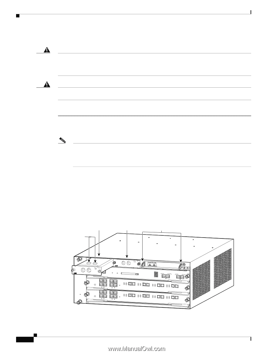
| Removing and Installing the 1000�W, 1300�W, 2500�W, 3000�W, 4000�W, and 6000�W AC-Input Power Sup... |
149 |
| Required Tools |
149 |
| Removing the 1000�W, 1300�W, 2500�W, 3000�W, 4000�W, and 6000�W AC-Input Power Supplies |
150 |
| Step�1 Turn the power switch to the Off (0) position on the power supply that you are removing. (... |
150 |
| Step�2 Disconnect the power cord from the power source. |
150 |
| Step�3 Loosen the screw on the cable retention device, and disconnect the power cord from the pow... |
150 |
| Step�4 Loosen the captive installation screw. (See Figure�4-6.) |
150 |
| Figure�4-6 AC-Input�Power Supply Front Panel |
150 |
| Step�5 Grasp the power supply handle with one hand, and slide the power supply part of the way ou... |
150 |
| Step�6 If the power supply bay is to remain empty, install a blank faceplate (Cisco part�number�7... |
150 |
| Figure�4-7 Handling an AC-Input Power Supply |
151 |
| Installing the 1000�W, 1300�W, 2500�W, 3000�W, 4000�W, and 6000�W AC-Input Power Supplies |
151 |
| Step�1 Ensure that the system (earth) ground connection has been made. For ground connection inst... |
151 |
| Step�2 If necessary, remove the blank faceplate (Cisco part�number�700-03104-01) from the chassis... |
151 |
| Step�3 Verify that the power switch is in the Off (0) position on the power supply that you are i... |
151 |
| Step�4 Grasp the power supply handle with one hand. Place your other hand underneath the power su... |
152 |
| Step�5 Tighten the power supply captive installation screw. (See�Figure�4-6.) |
152 |
| Step�6 Plug the power cord into the power supply, and tighten the screw on the cable retention de... |
152 |
| Step�7 Connect the other end of the power cord to an AC-input power source. |
152 |
| Step�8 Turn the power switch to the On (|) position on the power supply. Switching the power swit... |
152 |
| Step�9 Verify the power supply operation by ensuring that the power supply front panel LEDs are i... |
152 |
| Removing and Installing the DC-Input Power Supplies |
153 |
| Removing and Installing a 950�W DC-Input Power Supply |
153 |
| Tools Required |
153 |
| Removing a 950�W DC-Input Power Supply |
154 |
| Step�1 Identify which PEM is connected to the power supply you are removing (PEM�1 or PEM�2). Ver... |
154 |
| Step�2 Loosen the captive installation screws on the power supply. (See Figure�4-9.) |
154 |
| Step�3 Grasp the power supply handle with one hand, and slide the power supply part of the way ou... |
154 |
| Step�4 If the power supply bay is to remain empty, install a blank power supply filler plate (Cis... |
154 |
| Figure�4-8 Catalyst 6503 Switch—DC-Input PEM Location |
154 |
| Figure�4-9 950�W DC-Input Power Supply Captive Installation Screws |
155 |
| Figure�4-10 Catalyst 6503 Switch—Handling a DC-Input Power Supply |
155 |
| Installing a 950�W DC-Input Power Supply |
156 |
| Step�1 Ensure that the system (earth) ground connection has been made. For ground connection inst... |
156 |
| Step�2 Verify that power is off to the DC circuit connected to the DC PEM for the power supply th... |
156 |
| Step�3 Grasp the power supply handle with one hand. Place your other hand underneath the power su... |
156 |
| Step�4 Tighten the power supply captive installation screws. (See Figure�4-9.) |
156 |
| Step�5 Verify that all connections to the DC PEM are secure. |
156 |
| Step�6 Remove any safety flags, lockout devices, or tape from the circuit breaker switch handle, ... |
156 |
| Step�7 Verify the power supply operation by ensuring that the power supply front panel LEDs are i... |
156 |
| Removing and Installing a 1300�W or 2500�W DC-Input Power Supply |
157 |
| Required Tools |
157 |
| Removing a 1300�W or 2500�W DC-Input Power Supply |
157 |
| Step�1 Verify that power is off to the DC circuit on the power supply that you are removing. As a... |
157 |
| Step�2 Turn the power switch to the Off (0) position on the power supply that you are removing. (... |
157 |
| Step�3 Remove the two screws securing the terminal block cover, and slide the cover off the termi... |
157 |
| Step�4 Disconnect the DC-input wires from the terminal block (see Figure�4-13 for the 1300�W DC p... |
158 |
| Step�5 Loosen the captive installation screw on the power supply. (See Figure�4-13 for the 1300�W... |
158 |
| Step�6 Grasp the power supply handle with one hand, and slide the power supply halfway out of the... |
158 |
| Step�7 If the power supply bay is to remain empty, install a blank faceplate (Cisco�part�number�7... |
158 |
| Figure�4-11 DC-Input�Power Supply Front Panel (WS-CDC-1300W) |
158 |
| Figure�4-12 DC-Input�Power Supply Front Panel (WS-CDC-2500W) |
159 |
| Figure�4-13 DC-Input Wire Connections on the Terminal Block (WS-CDC-1300W) |
159 |
| Figure�4-14 DC-Input Wire Connections on the Terminal Block (WS-CDC-2500W) |
160 |
| Figure�4-15 Handling a DC-Input Power Supply |
161 |
| Installing a 1300�W or 2500�W DC-Input Power Supply |
162 |
| Step�1 Ensure that the system (earth) ground connection has been made. For ground connection inst... |
162 |
| Step�2 Verify that power is off to the DC circuit on the power supply that you are installing. As... |
162 |
| Step�3 Verify that the power switch is in the Off (0) position on the power supply that you are i... |
162 |
| Step�4 Grasp the power supply handle with one hand, and place your other hand underneath the powe... |
162 |
| Step�5 Tighten the power supply captive installation screw. (See Figure�4-11 for the 1300�W DC po... |
162 |
| Step�6 Remove the two screws securing the terminal block cover, and slide the cover off of the te... |
162 |
| Step�7 Attach the appropriate lugs to the DC-input wires. The maximum width of a lug is 0.300 inc... |
163 |
| Step�8 Connect the DC-input wires to the terminal block (see Figure�4-16 for the 1300�W DC power ... |
163 |
| Step�9 After ensuring that all wire connections are secure, reinstall the terminal block cover. |
163 |
| Step�10 Remove any safety flag and lockout devices or any tape from the circuit breaker switch ha... |
163 |
| Step�11 Turn the power switch to the On (|) position on the power supply. Turning on the power sw... |
163 |
| Step�12 Verify the power supply operation by ensuring that the power supply front panel LEDs are ... |
163 |
| Figure�4-16 DC-Input�Power Supply Connectors (WS-CDC-1300W) |
164 |
| Figure�4-17 DC-Input�Power Supply Connectors (WS-CDC-2500W) |
164 |
| Removing and Installing the 2700�W DC-Input Power Supply |
165 |
| Required Tools |
165 |
| Removing a 2700�W DC-Input Power Supply |
165 |
| Step�1 Verify that power is off to the DC circuit on the power supply that you are removing. As a... |
165 |
| Step�2 Remove the four screws securing the terminal block cover, and slide the cover off the term... |
165 |
| Figure�4-18 DC-Input Front Panel for 2700-W DC-Input Power Supply |
166 |
| Step�3 Remove the two screws securing each of the cable holder covers, and remove the cable holde... |
166 |
| Step�4 Disconnect the DC-input wires from the terminal block (Figure�4-19) in this order: |
166 |
| Step�5 Remove the two tie-wraps from the ground cable. If there is a long cable tie-wrap securing... |
166 |
| Step�6 Loosen the captive installation screws on the power supply. (See Figure�4-18.) |
166 |
| Step�7 Grasp both power supply handles, as shown in Figure�4-19, and slide the power supply compl... |
167 |
| Figure�4-19 Handling a DC-Input Power Supply |
167 |
| Step�8 If the power supply bay is to remain empty, install a blank power supply filler plate (Cis... |
167 |
| Installing a 2700�W DC-Input Power Supply |
167 |
| Step�1 Ensure that the system (earth) ground connection has been made. For ground connection inst... |
167 |
| Step�2 Remove the plastic bag attached to the front panel and put aside. This bag contains two pl... |
167 |
| Step�3 Verify that power is off to the DC circuit on the power supply that you are installing. As... |
167 |
| Figure�4-20 Handling the Power Supply |
168 |
| Step�4 Tighten the power supply captive installation screws. (See Figure�4-21.) |
168 |
| Figure�4-21 Power Supply Captive Installation Screws |
168 |
| Figure�4-22 DC-Input Front Panel for 2700-W DC-Input Power Supply |
169 |
| Step�5 Remove the four screws securing the terminal block cover, and slide the cover off of the t... |
169 |
| Step�6 Attach the appropriate lugs to the DC-input wires. The maximum width of a lug is 0.300 inc... |
169 |
| Step�7 Connect the DC-input wires to the 2700�W power supply terminal block (Figure�4-22) in this... |
170 |
| Step�8 Secure the ground cable to the cable holder with the two cable-ties. |
170 |
| Step�9 Retrieve the cable holder covers from the plastic bag and attach to the front panel at the... |
170 |
| Step�10 Secure the terminal block cover using four screws and the terminal block barriers with tw... |
170 |
| Step�11 Turn on the DC inputs and verify power supply operation by checking that the power supply... |
170 |
| Figure�4-23 DC-Input Wires on Left Side |
170 |
| Removing and Installing a 4000�W DC-Input Power Supply |
171 |
| Required Tools |
171 |
| Removing a 4000�W DC-Input Power Supply |
171 |
| Step�1 Verify that power is off to the DC circuit connected to the DC-input power supply that you... |
171 |
| Step�2 Turn the power switch to the Off (0) position on the power supply that you are removing. (... |
171 |
| Figure�4-24 DC-Input Front Panel for 4000-W DC-Input Power Supply |
172 |
| Step�3 Remove the two screws securing the outer terminal block cover, and remove the cover from t... |
173 |
| Step�4 Remove the two screws securing the left inner terminal block cover, remove the cover, and ... |
173 |
| Step�5 Remove the plastic insulator from over the terminal area. (See Figure�4-25.) |
173 |
| Step�6 Disconnect the DC-input wires from the terminal block in this order: |
173 |
| Figure�4-25 DC-Input Wire Connections for 4000-W DC-Input Power Supply |
173 |
| Step�7 Loosen the captive installation screw on the power supply. (See Figure�4-25.) |
174 |
| Step�8 Grasp the power supply handle with one hand, and slide the power supply part of the way ou... |
174 |
| Figure�4-26 Handling a 4000�W DC-Input Power Supply |
174 |
| Step�9 If the power supply bay is to remain empty, install a blank power supply filler plate (Cis... |
174 |
| Installing a 4000�W DC-Input Power Supply |
175 |
| Table�4-2 4000�W DC-Input Power Supply Installation Options |
175 |
| Figure�4-27 4000�W DC-Input Power Supply Front Panel |
176 |
| Installing the 4000�W Power Supply (Wiring for 2700�W Operation; Left Power Bay) |
177 |
| Step�1 Ensure that the system (earth) ground connection has been made. For ground connection inst... |
177 |
| Step�2 Verify that power is off to the DC circuit that is connected to the power supply that you ... |
177 |
| Step�3 Prepare the source DC-input power cables by attaching the appropriately sized lugs. |
177 |
| Figure�4-28 DC Power Cable Lug |
177 |
| Step�4 Grasp the power supply handle with one hand, and place your other hand underneath the powe... |
178 |
| Figure�4-29 Handling a 4000�W DC-Input Power Supply |
178 |
| Step�5 Tighten the power supply captive installation screws. (See Figure�4-27.) |
178 |
| Step�6 Remove the two screws that secure the outer terminal block cover, and remove the cover fro... |
178 |
| Step�7 Remove the two screws that secure the left inner terminal block cover, remove the cover, a... |
178 |
| Step�8 Place both plastic insulators over the terminal areas, aligning the circular holes in insu... |
178 |
| Step�9 Wrap the large perforated flaps around each pair of conductors, inserting each locking tab... |
179 |
| Step�10 From the left side of the power supply, connect the DC-input wires to the left power supp... |
179 |
| Figure�4-30 DC-Input Wire Connections for 2700�W Operation (Left-Side Power Bay) |
179 |
| Step�11 From the left side of the power supply, connect the DC-input wires to TB1 in this order: |
179 |
| Step�12 Position and secure the left and the right inner terminal block covers. |
180 |
| Step�13 Secure outer terminal block cover. |
180 |
| Step�14 If you are installing a second power supply operating at 2700�W in the right-side power s... |
180 |
| Step�15 After you confirm that all installation steps are completed correctly, remove any safety ... |
180 |
| Step�16 Turn the power switch to the On (|) position on the power supply. Turning on the power sw... |
180 |
| Step�17 Verify the power supply operation by ensuring that the power supply front panel LEDs are ... |
180 |
| Installing the 4000�W Power Supply (Wiring for 2700�W Operation; Right Power Bay) |
180 |
| Step�1 Ensure that the system (earth) ground connection has been made. For ground connection inst... |
180 |
| Step�2 Verify that power is off to the DC circuit that is connected to the power supply that you ... |
180 |
| Step�3 Prepare the source DC-input power cables by attaching the appropriately sized lugs. |
180 |
| Figure�4-31 DC Power Cable Lug |
181 |
| Step�4 Grasp the power supply handle with one hand, and place your other hand underneath the powe... |
181 |
| Figure�4-32 Handling a 4000�W DC-Input Power Supply |
181 |
| Step�5 Tighten the power supply captive installation screws. |
181 |
| Step�6 Remove the two screws that secure the outer terminal block cover, and remove the cover fro... |
182 |
| Step�7 Remove the two screws that secure the left inner terminal block cover, remove the cover, a... |
182 |
| Step�8 Place both plastic insulators over the terminal areas, aligning the circular holes in insu... |
182 |
| Step�9 Wrap the large perforated flaps around each pair of conductors, inserting each locking tab... |
182 |
| Step�10 From the right side of the power supply, connect the DC-input wires to the left power sup... |
182 |
| Figure�4-33 DC-Input Wire Connections for 2700�W Operation (Right-Side Power Bay) |
183 |
| Step�11 Position and secure the left and right inner terminal block covers. |
183 |
| Step�12 Using the cable tie provided, place the cable tie through the slot at the top of the righ... |
183 |
| Step�13 Secure outer terminal block cover. |
183 |
| Step�14 After you confirm that all installation steps are completed correctly, remove any safety ... |
183 |
| Step�15 Turn the power switch to the On (|) position on the power supply. Turning on the power sw... |
183 |
| Step�16 Verify the power supply operation by ensuring that the power supply front panel LEDs are ... |
183 |
| Installing the 4000�W Power Supply (Wiring for 4000�W Operation; Left Power Bay) |
184 |
| Step�1 Ensure that the system (earth) ground connection has been made. For ground connection inst... |
184 |
| Step�2 Verify that power is off to the DC circuit that is connected to the power supply that you ... |
184 |
| Step�3 Prepare the source DC-input power cables by attaching the appropriately sized lugs. |
184 |
| Figure�4-34 DC Power Cable Lug |
184 |
| Step�4 Grasp the power supply handle with one hand, and place your other hand underneath the powe... |
185 |
| Figure�4-35 Handling a 4000�W DC-Input Power Supply |
185 |
| Step�5 Tighten the power supply captive installation screws. |
185 |
| Step�6 Remove the two screws that secure the outer terminal block cover, and remove the cover fro... |
185 |
| Step�7 Remove the two screws that secure the left inner terminal block cover, remove the cover, a... |
185 |
| Step�8 Place both plastic insulators over the terminal areas, aligning the circular holes in insu... |
185 |
| Step�9 Wrap the large perforated flaps around each pair of conductors, inserting each locking tab... |
185 |
| Step�10 From the left side of the power supply, connect the DC-input wires to the left power supp... |
186 |
| Step�11 From the left side of the power supply, connect the DC-input wires to the right power sup... |
186 |
| Figure�4-36 DC-Input Wire Connections for 4000�W Operation (Left-Side Power Bay) |
186 |
| Step�12 Using the cable tie provided, place the cable tie through the slot at the top of the left... |
187 |
| Step�13 Secure the outer block cover. |
187 |
| Step�14 Position and secure the left and right inner terminal block covers. |
187 |
| Step�15 Secure the outer terminal block cover. |
187 |
| Step�16 If you are installing a second power supply that operates at 4000�W in the right side pow... |
187 |
| Step�17 After you confirm that all installation steps are completed correctly, remove any safety ... |
187 |
| Step�18 Turn the power switch to the On (|) position on the power supply. Turning on the power sw... |
187 |
| Step�19 Verify the power supply operation by ensuring that the power supply front panel LEDs are ... |
187 |
| Installing the 4000�W Power Supply (Wiring for 4000�W Operation; Right Power Bay) |
187 |
| Step�1 Ensure that the system (earth) ground connection has been made. For ground connection inst... |
187 |
| Step�2 Verify that power is off to the DC circuit that is connected to the power supply that you ... |
187 |
| Step�3 Prepare the source DC-input power cables by attaching the appropriately sized lugs. |
188 |
| Figure�4-37 DC Power Cable Lug |
188 |
| Step�4 Grasp the power supply handle with one hand, and place your other hand underneath the powe... |
188 |
| Figure�4-38 Handling a 4000�W DC-Input Power Supply |
188 |
| Step�5 Tighten the power supply captive installation screws. |
189 |
| Step�6 Remove the two screws that secure the outer terminal block cover, and remove the cover fro... |
189 |
| Step�7 Remove the two screws that secure the left inner terminal block cover, remove the cover, a... |
189 |
| Step�8 Place both plastic insulators over the terminal areas, aligning the circular holes in insu... |
189 |
| Step�9 Wrap the large perforated flaps around each pair of conductors, inserting each locking tab... |
189 |
| Step�10 From the right side of the power supply, connect the DC-input wires to the right power su... |
189 |
| Step�11 From the right side of the power supply, connect the DC-input wires to the left power sup... |
189 |
| Figure�4-39 DC-Input Wire Connections for 4000�W Operation (Right-Side Power Bay) |
190 |
| Step�12 Using the cable tie provided, place the cable tie through the slot at the top of the righ... |
190 |
| Step�13 Position and secure the left and right inner terminal block covers. |
190 |
| Step�14 Secure the outer block cover. |
190 |
| Step�15 After you confirm that all installation steps are completed correctly, remove any safety ... |
190 |
| Step�16 Turn the power switch to the On (|) position on the power supply. Turning on the power sw... |
191 |
| Step�17 Verify the power supply operation by ensuring that the power supply front panel LEDs are ... |
191 |
| Removing and Installing the Power Entry Modules (PEMs) |
191 |
| Figure�4-40 Catalyst 6503—PEM Location |
191 |
| Figure�4-41 Catalyst 6503 Switch—Power Supply Location |
192 |
| Required Tools |
192 |
| Removing the AC-Input PEM |
192 |
| Step�1 Turn the power switch to the Off (0) position on the PEM that you are removing. (See�Figur... |
192 |
| Step�2 Disconnect the power cord from the power source. Do not touch the metal prongs on the powe... |
192 |
| Step�3 Remove the power cord from the power connection on the PEM. Do not touch the metal prongs ... |
192 |
| Step�4 Loosen the captive installation screws. (See Figure�4-42.) |
192 |
| Step�5 Grasp the PEM with one hand, and slide it part of the way out of the chassis. Place your o... |
192 |
| Step�6 If the PEM bay is to remain empty, install a blank PEM filler plate (Cisco part�number�800... |
192 |
| Figure�4-42 AC-Input PEM (PEM-20A-AC+ Shown) |
193 |
| Figure�4-43 Handling a PEM |
193 |
| Installing the AC-Input PEM |
193 |
| Step�1 Ensure that the system (earth) ground connection has been made. For ground connection inst... |
193 |
| Step�2 If necessary, remove the blank PEM filler plate (Cisco part�number 800-16719-01) from the ... |
193 |
| Step�3 Grasp the PEM with one hand. Place your other hand underneath the PEM, as shown in Figure�... |
193 |
| Step�4 Tighten the PEM captive installation screws. (See�Figure�4-42.) |
193 |
| Step�5 Plug the power cord into the PEM. (See Appendix�A for a list of supported AC power cords.) |
194 |
| Step�6 Connect the other end of the power cord to an AC-input power source. |
194 |
| Step�7 Turn the power switch to the On (|) position on the PEM. |
194 |
| Removing the DC-Input PEM |
194 |
| Step�1 Verify that power is off to the DC circuit for the PEM that you are removing. As an added ... |
194 |
| Step�2 Loosen the captive installation screws on the PEM. (See Figure�4-44.) |
194 |
| Step�3 Slide the PEM part way out of the chassis so that you have access to the PEM terminal bloc... |
194 |
| Step�4 Disconnect the DC-input wires from the PEM terminal block in this order: |
194 |
| Step�5 Grasp the PEM with one hand, and place your other hand underneath the PEM, as shown in Fig... |
195 |
| Step�6 If the PEM bay is to remain empty, install a blank PEM filler plate (Cisco part�number�800... |
195 |
| Figure�4-44 DC-Input PEM |
195 |
| Figure�4-45 DC-Input PEM Terminal Block Screws |
195 |
| Figure�4-46 Handling a DC-Input PEM |
195 |
| Installing the DC-Input PEM |
196 |
| Step�1 Ensure that the system (earth) ground connection has been made. For ground connection inst... |
196 |
| Step�2 Verify that power is off to the DC circuit for the PEM that you are installing. As an adde... |
196 |
| Step�3 Install the PEM part way in the chassis so that you still have access to the PEM terminal ... |
196 |
| Step�4 Connect the DC-input wires to the terminal block in this order: |
196 |
| Step�5 After ensuring that all wire connections are secure, install the PEM in the bay. |
196 |
| Step�6 Tighten the power supply captive installation screws. (See�Figure�4-48.) |
196 |
| Step�7 Remove the safety flag, lockout devices, or tape from the circuit breaker switch handle, a... |
196 |
| Step�8 Verify the power supply operation by ensuring that the power supply front panel LEDs are i... |
196 |
| Figure�4-47 DC-Input PEM Terminal Block Screws |
197 |
| Figure�4-48 DC-Input�PEM |
197 |
| Removing and Installing the Fan Assembly |
197 |
| Required Tools |
197 |
| Removing the Fan Assembly |
197 |
| Step�1 Locate the fan assembly as follows: |
198 |
| Step�2 Loosen the two captive installation screws by turning them counterclockwise. |
198 |
| Step�3 Grasp the fan assembly with both hands, and pull it outward; rock it gently, if necessary,... |
198 |
| Step�4 Pull the fan assembly clear of the chassis, and put it in a safe place. |
198 |
| Figure�4-49 Fan Assembly: Catalyst 6503 and Catalyst 6503-E Switches |
199 |
| Figure�4-50 Fan Assembly: Catalyst 6504-E Switch |
199 |
| Figure�4-51 Fan Assembly: Catalyst 6506 and Catalyst 6506-E Switches |
200 |
| Figure�4-52 Fan Assembly: Catalyst 6509 and Catalyst 6509-E Switches |
201 |
| Figure�4-53 Fan Assembly: Catalyst 6509-NEB Switch |
202 |
| Figure�4-54 Fan Assembly: Catalyst 6509-NEB-A Switch |
203 |
| Figure�4-55 Accessing the Fan Trays on the Catalyst 6509-NEB-A Switch |
204 |
| Figure�4-56 Fan Assembly: Catalyst 6513 Switch |
204 |
| Installing the Fan Assembly |
205 |
| Step�1 Hold the fan assembly with the fans facing to the right and the FAN STATUS LED at the bottom. |
205 |
| Step�2 Place the fan assembly into the front chassis cavity so that it rests on the chassis, and ... |
205 |
| Step�3 Push the fan assembly into the chassis until the power connector seats in the backplane an... |
205 |
| Step�4 Tighten the captive installation screws. |
205 |
| Checking the Installation |
205 |
| Step�1 Listen for the fans; you should immediately hear them operating. If you do not hear them, ... |
205 |
| Step�2 Verify that the FAN STATUS LED is green. If the LED is red, one or more of the fans are fa... |
205 |
| Step�3 If after several attempts the fans do not operate or if you experience trouble with the in... |
205 |
| Installing the Air Filter Assembly on a Catalyst 6509-NEB-A Switch (Optional) |
206 |
| Table�4-3 Air Filter Part Numbers |
206 |
| Step�1 Remove the intake panel by unscrewing four thumbscrews. (See Figure�4-57.) |
206 |
| Figure�4-57 Removing the Intake Panel |
206 |
| Step�2 Install the new intake panel by tightening four thumbscrews. (See Figure�4-58.) |
206 |
| Figure�4-58 Installing the New Intake Panel |
207 |
| Step�3 Remove the inner filter retainer from the filter cage assembly by depressing the thumb loo... |
207 |
| Figure�4-59 Removing the Inner Filter Retainer |
208 |
| Step�4 Place the foam filter over the filter retainer. (See Figure�4-60.) |
208 |
| Step�5 Slide the retainer and filter into the cage assembly. |
208 |
| Figure�4-60 Placing the Foam Filter Over the Filter Retainer |
209 |
| Step�6 Install the filter assembly with the tabs facing the floor, as follows: |
209 |
| Figure�4-61 Installing the Filter Assembly |
210 |
| A |
211 |
| Power Supply Specifications |
211 |
| Table�A-1 Catalyst 6500 Series Power Supplies |
211 |
| Power Supply Compatibility Matrix |
212 |
| Table�A-2 Catalyst�6500 Series Switch Supported Power Supply Configurations� |
212 |
| 950�W AC-Input and DC-Input Power Supplies |
214 |
| Figure�A-1 950�W AC- and DC-Input Power Supplies |
214 |
| Figure�A-2 950�W AC-Input PEM (PEM-15A-AC) |
214 |
| Figure�A-3 DC Power Entry Module (PEM) |
215 |
| 950�W Power Supply Specifications |
215 |
| Table�A-3 950 W AC-Input and DC-Input Power Supplies Specifications� |
215 |
| 950�W Power Supply AC Power Cords |
218 |
| Table�A-4 950�W AC-Input Power Supply Power Cords |
218 |
| 1000�W AC-Input Power Supply |
219 |
| Figure�A-4 1000�W AC-Input Power Supply |
219 |
| 1000�W Power Supply Specifications |
220 |
| Table�A-5 1000�W Power Supply Specifications� |
220 |
| 1000�W Power Supply AC Power Cords |
222 |
| Table�A-6 1000�W AC-Input Power Supply Power Cords |
222 |
| 1300�W AC-Input and DC-Input Power Supplies |
223 |
| Figure�A-5 1300�W AC-input Power Supply |
223 |
| Figure�A-6 1300�W DC-Input Power Supply |
223 |
| 1300�W Power Supply Specifications |
224 |
| Table�A-7 1300�W AC-Input and DC-Input Power Supplies Specifications� |
224 |
| 1300�W Power Supply AC Power Cords |
227 |
| Table�A-8 1300�W Power Supply AC Power Cords |
227 |
| 1400�W AC-Input Power Supply |
228 |
| Figure�A-7 1400�W AC-Input Power Supply (PWR-1400-AC) |
228 |
| Figure�A-8 1400�W AC-Input PEM (PEM-20A-AC+) |
228 |
| 1400�W Power Supply Specifications |
229 |
| Table�A-9 1400�W Power Supply Specifications� |
229 |
| 1400�W Power Supply AC Power Cords |
230 |
| Table�A-10 1400�W Power Supply AC Power Cords� |
230 |
| 2500�W AC-Input and DC-Input Power Supplies |
232 |
| Figure�A-9 2500�W AC-Input Power Supply |
232 |
| Figure�A-10 2500�W DC-input Power Supply |
233 |
| 2500�W Power Supply Specifications |
233 |
| Table�A-11 2500�W Power Supply Specifications� |
233 |
| 2500�W Power Supply AC Power Cords |
237 |
| Table�A-12 2500�W Power Supply AC Power Cords |
237 |
| 2700�W AC-Input and DC-Input Power Supplies |
238 |
| Figure�A-11 2700�W AC-Input Power Supply |
238 |
| Figure�A-12 2700�W DC-input Power Supply |
239 |
| 2700�W Power Supply Specifications |
240 |
| Table�A-13 2700�W Power Supply Specifications� |
240 |
| 2700�W Power Supply AC Power Cords |
243 |
| Table�A-14 2700�W Power Supply AC Power Cords |
243 |
| 3000�W AC-Input Power Supply |
244 |
| Figure�A-13 3000�W AC-Input Power Supply |
244 |
| 3000�W Power Supply Specifications |
245 |
| Table�A-15 3000�W Power Supply Specifications� |
245 |
| 3000�W Power Supply AC Power Cords |
247 |
| Table�A-16 3000�W Power Supply AC Power Cords |
247 |
| 4000�W AC-Input and DC-Input Power Supplies |
248 |
| Figure�A-14 4000�W AC-Input Power Supply |
248 |
| Figure�A-15 4000�W DC-Input Power Supply |
249 |
| 4000�W Power Supply Specifications |
249 |
| Table�A-17 4000�W AC-Input and DC-Input Power Supplies Specifications� |
249 |
| 4000�W Power Supply AC Power Cords |
252 |
| Table�A-18 4000�W Power Supply AC Power Cords |
252 |
| 6000�W AC-Input Power Supply |
253 |
| Figure�A-16 6000�W AC-Input Power Supply |
253 |
| 6000�W Power Supply Specifications |
254 |
| Table�A-19 6000�W AC-Input Power Supply Specifications� |
254 |
| 6000�W Power Supply AC Power Cords |
256 |
| Table�A-20 6000�W Power Supply AC Power Cords� |
256 |
| AC Power Cord Illustrations |
257 |
| Figure�A-17 CAB-AC10A-90L-AU= |
257 |
| Figure�A-18 CAB-AC10A-90L-EU= |
258 |
| Figure�A-19 CAB-AC10A-90L-IT= |
258 |
| Figure�A-20 CAB-AC15A-90L-US= |
258 |
| Figure�A-21 CAB-AC10A-90L-UK= |
259 |
| Figure�A-22 CAB-7KACR= |
259 |
| Figure�A-23 CAB-7KACA= |
259 |
| Figure�A-24 CAB-7KACE= |
260 |
| Figure�A-25 CAB-7KACI= |
260 |
| Figure�A-26 CAB-7KAC-15= |
260 |
| Figure�A-27 CAB-7KACU= |
261 |
| Figure�A-28 CAB-7513ACR= |
261 |
| Figure�A-29 CAB-7513ACA= |
261 |
| Figure�A-30 CAB-7513ACE= |
262 |
| Figure�A-31 CAB-AC-2500W-ISRL |
262 |
| Figure�A-32 CAB-7513ACI= |
262 |
| Figure�A-33 CAB-7513AC= |
263 |
| Figure�A-34 CAB-AC16A-CH= |
263 |
| Figure�A-35 CAB-7513ACSA= |
263 |
| Figure�A-36 CAB-ACS-10= |
264 |
| Figure�A-37 CAB-7513ACU |
264 |
| Figure�A-38 CAB-AC-2500W-EU |
264 |
| Figure�A-39 CAB-AC-2500W-INT= |
265 |
| Figure�A-40 CAB-AC-2500W-US1= |
265 |
| Figure�A-41 CAB-AC-C6K-TWLK= |
265 |
| Figure�A-42 CAB-ACS-16= |
266 |
| Figure�A-43 CAB-AC-16A-AUS= |
266 |
| Figure�A-44 CAB-C19-CBN= |
266 |
| Figure�A-45 WS-CAC-4000W-INT= |
267 |
| Figure�A-46 WS-CAC-4000W-US= |
267 |
| Power Supply Redundancy |
267 |
| Table�A-21 Power Supply Redundancy� |
268 |
| Table�A-22 Effects of Power Supply Configuration Changes� |
268 |
| B |
273 |
| Transceivers, Module Connectors, and Cable Specifications |
273 |
| Transceivers |
273 |
| 100-MB Transceiver Modules |
274 |
| Table�B-1 100-MB Transceiver Modules Descriptions |
274 |
| Figure�B-1 100-MB SFP Transceiver Module |
274 |
| 1-GB Transceiver Modules |
275 |
| Table�B-2 1-GB Transceiver Modules Descriptions� |
275 |
| Table�B-3 GBIC Transceiver Module Cabling Specifications� |
277 |
| Table�B-4 SFP Transceiver Module Cabling Specifications� |
278 |
| Figure�B-2 1000BASE-T GBIC Transceiver Module (WS-G5483) |
278 |
| Figure�B-3 1000BASE-X GBIC Transceiver Modules (WS-G5484, WS-G5486, and WS-G5487) |
278 |
| Figure�B-4 1000BASE-T SFP Transceiver Module (GLC-T) |
279 |
| Figure�B-5 1000BASE-X SFP Transceiver Modules (GLC-SX-MM, GLC-LH-SM, and GLC-ZX-SM) |
279 |
| 10-GB Transceiver Modules |
280 |
| Table�B-5 10-GB Transceiver Modules |
280 |
| Table�B-6 10-GB XENPAK Transceiver Modules Specifications and Cabling Distances� |
281 |
| Figure�B-6 10-Gigabit XENPACK Transceiver Module |
282 |
| WDM Transceiver Modules |
282 |
| Table�B-7 WDM Transceiver Modules Descriptions� |
282 |
| Table�B-8 CWDM GBIC Transceivers |
284 |
| Figure�B-7 CWDM GBIC Transceiver |
285 |
| Table�B-9 DWDM GBIC Transceiver Module Product Numbers and ITU Channel Numbers� |
285 |
| Figure�B-8 DWDM GBIC Transceiver Module |
286 |
| Table�B-10 CWDM SFP Transceiver Modules� |
286 |
| Figure�B-9 CWDM SFP Transceiver |
287 |
| Table�B-11 DWDM XENPAK Transceiver Module Product Numbers and ITU Channel Numbers� |
287 |
| Figure�B-10 DWDM XENPAK Transceiver Module |
289 |
| Module Connectors |
289 |
| RJ-45 Connector |
289 |
| Figure�B-11 RJ-45 Interface Cable Connector |
290 |
| RJ-21 Connector |
290 |
| Figure�B-12 RJ-21 Telco Interface Cable Connectors |
291 |
| Table�B-12 RJ-21 Connector Pinout� |
292 |
| RJ-21 Connector (WS-X6624-FXS Only) |
293 |
| Table�B-13 RJ-21 Connector Pinout (WS-X6224-FXS Analog Interface Module Only) |
293 |
| SC Connector |
294 |
| Figure�B-13 SC Fiber-Optic Connector |
294 |
| MT-RJ Connector |
294 |
| Figure�B-14 MT-RJ Connector |
295 |
| LC Connector |
295 |
| Figure�B-15 LC Fiber Optic Connector |
295 |
| Cables |
296 |
| Table�B-14 10/100BASE-T Crossover Cable Pinout (MDI-X) |
296 |
| Figure�B-16 Twisted-Pair Crossover 10/100BASE-T Cable Schematic |
296 |
| Table�B-15 1000BASE-T Crossover Cable Pinout (MDI-X)� |
297 |
| Figure�B-17 Twisted-Pair Crossover 1000BASE-T Cable Schematic |
297 |
| Console Port Mode Switch |
298 |
| Identifying a Rollover Cable |
298 |
| Figure�B-18 Identifying a Rollover Cable |
298 |
| Console Port Mode 1 Signaling and Pinouts |
299 |
| DB-9 Adapter (for Connecting to a PC) |
299 |
| Table�B-16 Port Mode 1 Signaling and Pinouts (DB-9 Adapter) |
299 |
| DB-25 Adapter (for Connecting to a Terminal) |
299 |
| Table�B-17 Port Mode 1 Signaling and Pinouts (DB-25 Adapter)� |
299 |
| Modem Adapter |
300 |
| Table�B-18 Port Mode 1 Signaling and Pinouts (Modem Adapter)� |
300 |
| Console Port Mode 2 Signaling and Pinouts |
300 |
| Table�B-19 Port Mode 2 Signaling and Pinouts (Port Mode Switch Out)� |
300 |
| Mode-Conditioning Patch Cord |
301 |
| Patch Cord Configuration Example |
301 |
| Figure�B-19 Patch Cord Configuration |
301 |
| Patch Cord Installation |
302 |
| Figure�B-20 Patch Cord Installation |
302 |
| Differential Mode Delay |
302 |
| Figure�B-21 LED Transmission Compared to Laser Transmission |
303 |
| Cleaning the Fiber Optic Connectors |
303 |
| Step�1 Use a lint-free tissue soaked in 99 percent pure isopropyl alcohol to gently wipe the face... |
304 |
| Step�2 Remove any residual dust from the faceplate with clean, dry, oil-free compressed air. |
304 |
| Step�3 Use a magnifying glass or inspection microscope to inspect the ferrule at an angle. Do not... |
304 |
| C |
305 |
| Repacking the�Switch |
305 |
| Step�1 Set the chassis in the bottom pallet. (See�Figure�C-1.) |
305 |
| Step�2 Place the packing bag over the chassis. |
305 |
| Step�3 Place the front-packing material and power supply packing material around the chassis. |
305 |
| Step�4 Place the power supplies in the spaces provided in the power supply packing material. (See... |
305 |
| Step�5 Place the top-packing material over the top of the chassis and power supplies. |
305 |
| Step�6 Place the rack-mount kit and the accessory kit on the top-packing material. |
305 |
| Step�7 Place the outside carton over the entire package. |
305 |
| Step�8 Fold the outside carton down over the top and seal with packing tape. |
305 |
| Step�9 Wrap three packing straps tightly around the top and bottom of the package to hold the out... |
305 |
| Figure�C-1 Packing�Material |
306 |
| Figure�C-2 Final Package |
306 |
| D |
307 |
| Chassis and Module Power and Heat Values |
307 |
| Table�D-1 Power Requirements and Heat Dissipation—Chassis and Fan Trays� |
307 |
| Table�D-2 Power Requirements and Heat Dissipation—IP Phones |
308 |
| Table�D-3 Power Requirements and Heat Dissipation—Supervisor Engines� |
309 |
| Table�D-4 Power Requirements and Heat Dissipation—Modules� |
310 |
| E |
317 |
| Troubleshooting |
317 |
| Getting Started |
317 |
| Solving Problems at the System Component Level |
318 |
| Identifying Startup Problems |
319 |
| Step�1 Turn on the power supplies. You should immediately hear the system fan assembly begin to o... |
319 |
| Step�2 Verify that the LEDs on the supervisor engine light as follows: |
319 |
| Step�3 Verify that the STATUS LEDs on the supervisor engine and on each switching module are gree... |
319 |
| Step�4 If the startup information and system banner do not display at startup, refer to the Catal... |
319 |
| Troubleshooting the Power Supply |
320 |
| Step�1 Verify that the INPUT OK LED on the power supply is green. |
320 |
| Step�2 If you have a second (redundant) power supply, repeat Step 1 for this power supply. |
320 |
| Troubleshooting the Fan Assembly |
321 |
| Step�1 Verify that the FAN LED on the fan assembly is green. |
321 |
| Step�2 Verify that the FAN LED is red. |
321 |
| Troubleshooting Modules |
321 |
| Step�1 Verify that all status LEDs are on. |
321 |
| Step�2 If any status LEDs on the supervisor engine or any switching modules are red or off, the m... |
321 |
| STATUS LED Indications |
321 |
| Table�E-1 Environmental Monitoring for Supervisor Engine and Switching Modules� |
322 |
| Contacting Customer Service |
323 |
| Numerics |
325 |
| A |
326 |
| B |
327 |
| C |
327 |
| D |
330 |
| E |
330 |
| F |
331 |
| G |
331 |
| I |
331 |
| L |
331 |
| M |
332 |
| O |
332 |
| P |
332 |
| R |
333 |
| S |
333 |
| T |
334 |
| U |
335 |
| V |
335 |
| W |
335 |

 1
1 149
149 150
150 151
151 152
152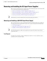 153
153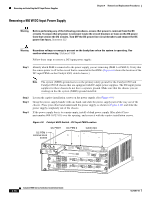 154
154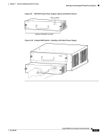 155
155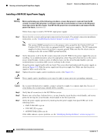 156
156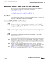 157
157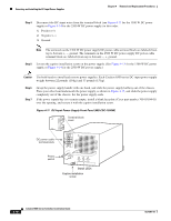 158
158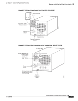 159
159