Cisco 6509 Installation Guide - Page 321
Troubleshooting the Fan Assembly, Troubleshooting Modules
 |
UPC - 746320196077
View all Cisco 6509 manuals
Add to My Manuals
Save this manual to your list of manuals |
Page 321 highlights
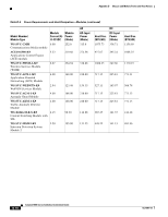
Appendix E Troubleshooting Troubleshooting the Fan Assembly Troubleshooting the Fan Assembly To isolate a fan assembly problem, follow these steps: Step 1 Step 2 Verify that the FAN LED on the fan assembly is green. If the FAN LED is not green, see the "Solving Problems at the System Component Level" section on page E-2 to determine whether or not the power subsystem is functioning properly. Verify that the FAN LED is red. • If the FAN LED is red, the fan assembly is not seated in the backplane or has malfunctioned. • To ensure that the fan assembly is seated properly, loosen the captive installation screws, remove the fan assembly, and reinstall it. • Tighten all captive installation screws, and then restart the system. • If the FAN LED is still red, the system detects an individual fan failure. Contact a customer service representative for instructions. Troubleshooting Modules To isolate a supervisor engine or switching module problem, follow these steps: Step 1 Step 2 Verify that all status LEDs are on. If any status LEDs on the supervisor engine or any switching modules are red or off, the module might have shifted out of its slot. Reseat the module until both ejector levers are at right angles to the rear of the chassis. Tighten the captive installation screws at the left and right of the module front panel, and restart the system. STATUS LED Indications The STATUS LEDs can indicate two alarm types: major and minor. Major alarms indicate a critical problem that could lead to the system being shut down. Minor alarms are for informational purposes only, giving you notice of a problem that could turn critical if corrective action is not taken. When the system has an alarm (major or minor) that indicates an overtemperature condition, the alarm is not canceled and no action is taken (such as a module reset or a shutdown) for 5 minutes. If the temperature falls 5°C (41°F) below the alarm threshold during this period, the alarm is canceled. Table E-1 lists the environmental indicators for the supervisor engine and switching modules. Note Refer to the Catalyst 6500 Series Switch Module Installation Guide for additional information on LEDs, including the supervisor engine SYSTEM LED. OL-5781-04 Catalyst 6500 Series Switches Installation Guide E-5
-
 1
1 -
2
-
3
-
4
-
5
-
6
-
7
-
8
-
9
-
10
-
11
-
12
-
13
-
14
-
15
-
16
-
17
-
18
-
19
-
20
-
21
-
22
-
23
-
24
-
25
-
26
-
27
-
28
-
29
-
30
-
31
-
32
-
33
-
34
-
35
-
36
-
37
-
38
-
39
-
40
-
41
-
42
-
43
-
44
-
45
-
46
-
47
-
48
-
49
-
50
-
51
-
52
-
53
-
54
-
55
-
56
-
57
-
58
-
59
-
60
-
61
-
62
-
63
-
64
-
65
-
66
-
67
-
68
-
69
-
70
-
71
-
72
-
73
-
74
-
75
-
76
-
77
-
78
-
79
-
80
-
81
-
82
-
83
-
84
-
85
-
86
-
87
-
88
-
89
-
90
-
91
-
92
-
93
-
94
-
95
-
96
-
97
-
98
-
99
-
100
-
101
-
102
-
103
-
104
-
105
-
106
-
107
-
108
-
109
-
110
-
111
-
112
-
113
-
114
-
115
-
116
-
117
-
118
-
119
-
120
-
121
-
122
-
123
-
124
-
125
-
126
-
127
-
128
-
129
-
130
-
131
-
132
-
133
-
134
-
135
-
136
-
137
-
138
-
139
-
140
-
141
-
142
-
143
-
144
-
145
-
146
-
147
-
148
-
149
-
150
-
151
-
152
-
153
-
154
-
155
-
156
-
157
-
158
-
159
-
160
-
161
-
162
-
163
-
164
-
165
-
166
-
167
-
168
-
169
-
170
-
171
-
172
-
173
-
174
-
175
-
176
-
177
-
178
-
179
-
180
-
181
-
182
-
183
-
184
-
185
-
186
-
187
-
188
-
189
-
190
-
191
-
192
-
193
-
194
-
195
-
196
-
197
-
198
-
199
-
200
-
201
-
202
-
203
-
204
-
205
-
206
-
207
-
208
-
209
-
210
-
211
-
212
-
213
-
214
-
215
-
216
-
217
-
218
-
219
-
220
-
221
-
222
-
223
-
224
-
225
-
226
-
227
-
228
-
229
-
230
-
231
-
232
-
233
-
234
-
235
-
236
-
237
-
238
-
239
-
240
-
241
-
242
-
243
-
244
-
245
-
246
-
247
-
248
-
249
-
250
-
251
-
252
-
253
-
254
-
255
-
256
-
257
-
258
-
259
-
260
-
261
-
262
-
263
-
264
-
265
-
266
-
267
-
268
-
269
-
270
-
271
-
272
-
273
-
274
-
275
-
276
-
277
-
278
-
279
-
280
-
281
-
282
-
283
-
284
-
285
-
286
-
287
-
288
-
289
-
290
-
291
-
292
-
293
-
294
-
295
-
296
-
297
-
298
-
299
-
300
-
301
-
302
-
303
-
304
-
305
-
306
-
307
-
308
-
309
-
310
-
311
-
312
-
313
-
314
-
315
-
 316
316 -
 317
317 -
 318
318 -
 319
319 -
 320
320 -
 321
321 -
 322
322 -
 323
323 -
 324
324 -
 325
325 -
 326
326 -
327
-
328
-
329
-
330
-
331
-
332
-
333
-
334
-
335
-
336
 |
 |
