Cisco 6509 Installation Guide - Page 90
Air Flow
 |
UPC - 746320196077
View all Cisco 6509 manuals
Add to My Manuals
Save this manual to your list of manuals |
Page 90 highlights
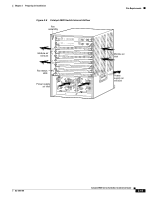
Site Requirements Chapter 2 Preparing for Installation Air Flow The system fan assembly provides cooling air for the supervisor engine and the switching modules. Table 2-2 lists the Catalyst 6500 series switch chassis along with the supported and unsupported fan trays. Table 2-3 lists the chassis air flow architecture and requirements for the Catalyst 6500 series switches. Sensors on the supervisor engine monitor the internal air temperatures. If the air temperature exceeds a preset threshold, the environmental monitor displays warning messages. The Catalyst 6500 series switch is designed to be installed in an environment where there is a sufficient volume of air available to cool the supervisor engines, modules, and power supplies. Any constraints placed on the free flow of air through the chassis or an elevated ambient air temperature can cause the switch to overheat and shut down. To maintain proper air circulation through the Catalyst 6500 switch chassis, we recommend that you maintain a minimum 6-inch (15 cm) separation between a wall and the chassis air intake or a wall and the chassis hot air exhaust. In situations where the switch chassis are installed in adjacent racks, you should allow a minimum of 12-inches (30.5 cm) between the air intake of one chassis and the hot air exhaust of another chassis. Failure to maintain adequate spacing between chassis can cause the switch chassis that is drawing in the hot air exhaust to overheat and fail. On Catalyst 6500 series chassis in which the airflow is from front to back, the chassis may be placed side-to-side. If you choose to install your Catalyst 6500 series switch in an enclosed or partially enclosed rack, we strongly recommend that you verify that your site meets the following guidelines: • Verify that there is a minimum of 6 inches (15 cm) of clearance between the sides of the rack and both the chassis air intake grill and the chassis air exhaust grill. • Verify that the ambient air temperature within the enclosed or partially enclosed rack is within the chassis operating temperature limits. After installing the chassis in the rack, power up the chassis and allow the chassis temperature to stabilize (approximately 2 hours). Measure the ambient air temperature at the chassis air intake grill and at the chassis air exhaust grill by positioning an external temperature probe approximately 1 inch (2.5 cm) away from the grills, in line with the chassis slot occupied by the supervisor engine. - If the ambient intake air temperature is less than 40°C (104°F), the rack meets the intake air temperature criterion. - If the ambient intake air temperature exceeds 40°C (104°F), the system might experience minor temperature alarms and is in danger of overheating. - If the ambient intake air temperature equals or is greater than 55°C (131°F), the system will experience a major temperature alarm and shut down. • Verify that the enclosed or partially enclosed rack allows an adequate flow of air through the switch chassis as follows: - If the difference between the measured intake air temperature and the exhaust air temperature does not exceed 10°C, there is sufficient airflow in the rack. - If the difference in air temperature exceeds 10° C, there is insufficient airflow to cool the chassis. Note The 10°C temperature differential between the intake and the exhaust must be determined by taking measurements using external digital temperature probes. Do not use the chassis internal temperature sensors to measure the temperature differential. 2-10 Catalyst 6500 Series Switches Installation Guide OL-5781-04
-
 1
1 -
2
-
3
-
4
-
5
-
6
-
7
-
8
-
9
-
10
-
11
-
12
-
13
-
14
-
15
-
16
-
17
-
18
-
19
-
20
-
21
-
22
-
23
-
24
-
25
-
26
-
27
-
28
-
29
-
30
-
31
-
32
-
33
-
34
-
35
-
36
-
37
-
38
-
39
-
40
-
41
-
42
-
43
-
44
-
45
-
46
-
47
-
48
-
49
-
50
-
51
-
52
-
53
-
54
-
55
-
56
-
57
-
58
-
59
-
60
-
61
-
62
-
63
-
64
-
65
-
66
-
67
-
68
-
69
-
70
-
71
-
72
-
73
-
74
-
75
-
76
-
77
-
78
-
79
-
80
-
81
-
82
-
83
-
84
-
 85
85 -
 86
86 -
 87
87 -
 88
88 -
 89
89 -
 90
90 -
 91
91 -
 92
92 -
 93
93 -
 94
94 -
 95
95 -
96
-
97
-
98
-
99
-
100
-
101
-
102
-
103
-
104
-
105
-
106
-
107
-
108
-
109
-
110
-
111
-
112
-
113
-
114
-
115
-
116
-
117
-
118
-
119
-
120
-
121
-
122
-
123
-
124
-
125
-
126
-
127
-
128
-
129
-
130
-
131
-
132
-
133
-
134
-
135
-
136
-
137
-
138
-
139
-
140
-
141
-
142
-
143
-
144
-
145
-
146
-
147
-
148
-
149
-
150
-
151
-
152
-
153
-
154
-
155
-
156
-
157
-
158
-
159
-
160
-
161
-
162
-
163
-
164
-
165
-
166
-
167
-
168
-
169
-
170
-
171
-
172
-
173
-
174
-
175
-
176
-
177
-
178
-
179
-
180
-
181
-
182
-
183
-
184
-
185
-
186
-
187
-
188
-
189
-
190
-
191
-
192
-
193
-
194
-
195
-
196
-
197
-
198
-
199
-
200
-
201
-
202
-
203
-
204
-
205
-
206
-
207
-
208
-
209
-
210
-
211
-
212
-
213
-
214
-
215
-
216
-
217
-
218
-
219
-
220
-
221
-
222
-
223
-
224
-
225
-
226
-
227
-
228
-
229
-
230
-
231
-
232
-
233
-
234
-
235
-
236
-
237
-
238
-
239
-
240
-
241
-
242
-
243
-
244
-
245
-
246
-
247
-
248
-
249
-
250
-
251
-
252
-
253
-
254
-
255
-
256
-
257
-
258
-
259
-
260
-
261
-
262
-
263
-
264
-
265
-
266
-
267
-
268
-
269
-
270
-
271
-
272
-
273
-
274
-
275
-
276
-
277
-
278
-
279
-
280
-
281
-
282
-
283
-
284
-
285
-
286
-
287
-
288
-
289
-
290
-
291
-
292
-
293
-
294
-
295
-
296
-
297
-
298
-
299
-
300
-
301
-
302
-
303
-
304
-
305
-
306
-
307
-
308
-
309
-
310
-
311
-
312
-
313
-
314
-
315
-
316
-
317
-
318
-
319
-
320
-
321
-
322
-
323
-
324
-
325
-
326
-
327
-
328
-
329
-
330
-
331
-
332
-
333
-
334
-
335
-
336
 |
 |
