Cisco 6509 Installation Guide - Page 156
Installing a 950 W DC-Input Power Supply
 |
UPC - 746320196077
View all Cisco 6509 manuals
Add to My Manuals
Save this manual to your list of manuals |
Page 156 highlights
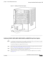
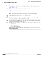
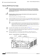
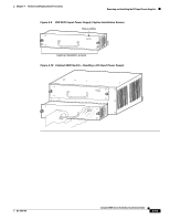
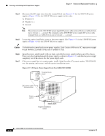
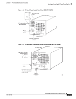
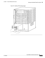
Removing and Installing the DC-Input Power Supplies Chapter 4 Removal and Replacement Procedures Installing a 950 W DC-Input Power Supply Warning Before performing any of the following procedures, ensure that power is removed from the DC circuits. To ensure that all power is removed, locate the circuit breakers or fuses on the DC power lines that service the DC circuits. Turn OFF the DC power line circuit breakers and remove the DC power line fuses. Statement 322 Follow these steps to install a 950 W DC-input power supply: Step 1 Ensure that the system (earth) ground connection has been made. For ground connection installation instructions, see the "Establishing the System Ground" section on page 3-22. Note The system (NEBS) ground serves as the primary safety ground for the Catalyst 6503 and Catalyst 6503-E chassis that are equipped with DC-input power supplies. The DC-input power supplies for these chassis do not have a separate ground. Make sure that the chassis you are working on has the system (NEBS) ground installed. Step 2 Step 3 Step 4 Verify that power is off to the DC circuit connected to the DC PEM for the power supply that you are installing. As an added precaution, place the appropriate safety flag and lockout devices at the source power circuit breaker, or place a piece of adhesive tape over the circuit breaker handle to prevent accidental power restoration while you are working on the circuit. Grasp the power supply handle with one hand. Place your other hand underneath the power supply, as shown in Figure 4-10. Slide the power supply into the power supply bay. Make sure that the power supply is fully seated in the bay. Tighten the power supply captive installation screws. (See Figure 4-9.) Caution Power supply captive installation screws must be tight to ensure protective grounding continuity. Caution In a system with dual power supplies, connect each power supply to a separate input line. In case of a line failure, the second source should still be available. Step 5 Step 6 Step 7 Verify that all connections to the DC PEM are secure. Remove any safety flags, lockout devices, or tape from the circuit breaker switch handle, and restore power by moving the circuit breaker switch handle to the On (|) position. Verify the power supply operation by ensuring that the power supply front panel LEDs are in the following states: • INPUT OK LED is green • FAN OK LED is green • OUTPUT FAIL LED is not lit If the LEDs indicate a power problem, see the "Identifying Startup Problems" section on page E-3. 4-16 Catalyst 6500 Series Switches Installation Guide OL-5781-04
-
 1
1 -
2
-
3
-
4
-
5
-
6
-
7
-
8
-
9
-
10
-
11
-
12
-
13
-
14
-
15
-
16
-
17
-
18
-
19
-
20
-
21
-
22
-
23
-
24
-
25
-
26
-
27
-
28
-
29
-
30
-
31
-
32
-
33
-
34
-
35
-
36
-
37
-
38
-
39
-
40
-
41
-
42
-
43
-
44
-
45
-
46
-
47
-
48
-
49
-
50
-
51
-
52
-
53
-
54
-
55
-
56
-
57
-
58
-
59
-
60
-
61
-
62
-
63
-
64
-
65
-
66
-
67
-
68
-
69
-
70
-
71
-
72
-
73
-
74
-
75
-
76
-
77
-
78
-
79
-
80
-
81
-
82
-
83
-
84
-
85
-
86
-
87
-
88
-
89
-
90
-
91
-
92
-
93
-
94
-
95
-
96
-
97
-
98
-
99
-
100
-
101
-
102
-
103
-
104
-
105
-
106
-
107
-
108
-
109
-
110
-
111
-
112
-
113
-
114
-
115
-
116
-
117
-
118
-
119
-
120
-
121
-
122
-
123
-
124
-
125
-
126
-
127
-
128
-
129
-
130
-
131
-
132
-
133
-
134
-
135
-
136
-
137
-
138
-
139
-
140
-
141
-
142
-
143
-
144
-
145
-
146
-
147
-
148
-
149
-
150
-
 151
151 -
 152
152 -
 153
153 -
 154
154 -
 155
155 -
 156
156 -
 157
157 -
 158
158 -
 159
159 -
 160
160 -
 161
161 -
162
-
163
-
164
-
165
-
166
-
167
-
168
-
169
-
170
-
171
-
172
-
173
-
174
-
175
-
176
-
177
-
178
-
179
-
180
-
181
-
182
-
183
-
184
-
185
-
186
-
187
-
188
-
189
-
190
-
191
-
192
-
193
-
194
-
195
-
196
-
197
-
198
-
199
-
200
-
201
-
202
-
203
-
204
-
205
-
206
-
207
-
208
-
209
-
210
-
211
-
212
-
213
-
214
-
215
-
216
-
217
-
218
-
219
-
220
-
221
-
222
-
223
-
224
-
225
-
226
-
227
-
228
-
229
-
230
-
231
-
232
-
233
-
234
-
235
-
236
-
237
-
238
-
239
-
240
-
241
-
242
-
243
-
244
-
245
-
246
-
247
-
248
-
249
-
250
-
251
-
252
-
253
-
254
-
255
-
256
-
257
-
258
-
259
-
260
-
261
-
262
-
263
-
264
-
265
-
266
-
267
-
268
-
269
-
270
-
271
-
272
-
273
-
274
-
275
-
276
-
277
-
278
-
279
-
280
-
281
-
282
-
283
-
284
-
285
-
286
-
287
-
288
-
289
-
290
-
291
-
292
-
293
-
294
-
295
-
296
-
297
-
298
-
299
-
300
-
301
-
302
-
303
-
304
-
305
-
306
-
307
-
308
-
309
-
310
-
311
-
312
-
313
-
314
-
315
-
316
-
317
-
318
-
319
-
320
-
321
-
322
-
323
-
324
-
325
-
326
-
327
-
328
-
329
-
330
-
331
-
332
-
333
-
334
-
335
-
336
 |
 |