Cisco 6509 Installation Guide - Page 302
Patch Cord Installation, Differential Mode Delay
 |
UPC - 746320196077
View all Cisco 6509 manuals
Add to My Manuals
Save this manual to your list of manuals |
Page 302 highlights
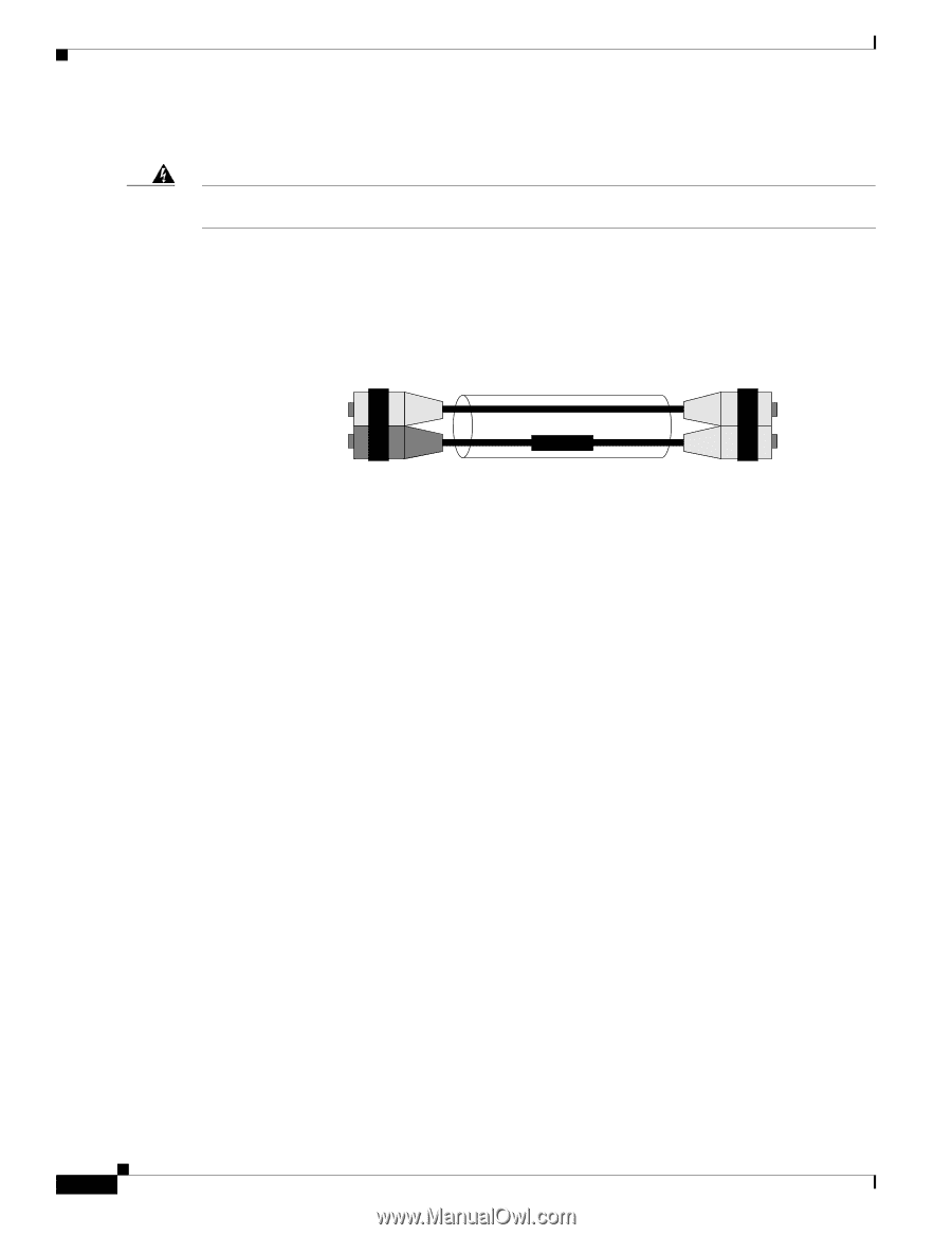
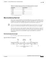
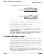
Cables Appendix B Transceivers, Module Connectors, and Cable Specifications Patch Cord Installation Warning Invisible laser radiation may be emitted from disconnected fibers or connectors. Do not stare into beams or view directly with optical instruments. Statement 1051 Plug the end of the patch cord labeled "To Equipment" into the GBIC. (See Figure B-20.) Plug the end labeled "To Cable Plant" into the patch panel. The patch cord is 9.8 feet (3 meters) long and has duplex SC male connectors at each end. Figure B-20 Patch Cord Installation To equipment To cable plant 13089 Differential Mode Delay When an unconditioned laser source designed for operation on an SMF cable is directly coupled to an MMF cable, differential mode delay (DMD) might occur. DMD can degrade the modal bandwidth of the fiber-optic cable. This degradation causes a decrease in the link span (the distance between the transmitter and the receiver) that can be reliably supported. The Gigabit Ethernet specification (IEEE 802.3z) outlines parameters for Ethernet communications at a gigabit-per-second rate. The specification offers a higher-speed version of Ethernet for backbone and server connectivity using existing deployed MMF cable by defining the use of laser-based optical components to propagate data over MMF cable. Lasers function at the baud rates and longer distances required for Gigabit Ethernet. The 802.3z Gigabit Ethernet Task Force has identified the DMD condition that occurs with particular combinations of lasers and MMF cable. The results create an additional element of jitter that can limit the reach of Gigabit Ethernet over MMF cable. With DMD, a single laser light pulse excites a few modes equally within an MMF cable. These modes, or light pathways, then follow two or more different paths. These paths might have different lengths and transmission delays as the light travels through the cable. With DMD, a distinct pulse propagating down the cable no longer remains a distinct pulse or, in extreme cases, might become two independent pulses. Strings of pulses can interfere with each other making it difficult to recover data. DMD does not occur in all deployed fibers; it occurs with certain combinations of worst-case fibers and worst-case transceivers. Gigabit Ethernet experiences this problem because of its very high baud rate and its long MMF cable lengths. SMF cable and copper cable are not affected by DMD. MMF cable has been tested for use only with LED sources. LEDs can create an overfilled launch condition within the fiber-optic cable. The overfilled launch condition describes the way LED transmitters couple light into the fiber-optic cable in a broad spread of modes. Similar to a light bulb radiating light into a dark room, the generated light that shines in multiple directions can overfill the existing cable space and excite a large number of modes. (See Figure B-21.) B-30 Catalyst 6500 Series Switches Installation Guide OL-5781-04
-
 1
1 -
2
-
3
-
4
-
5
-
6
-
7
-
8
-
9
-
10
-
11
-
12
-
13
-
14
-
15
-
16
-
17
-
18
-
19
-
20
-
21
-
22
-
23
-
24
-
25
-
26
-
27
-
28
-
29
-
30
-
31
-
32
-
33
-
34
-
35
-
36
-
37
-
38
-
39
-
40
-
41
-
42
-
43
-
44
-
45
-
46
-
47
-
48
-
49
-
50
-
51
-
52
-
53
-
54
-
55
-
56
-
57
-
58
-
59
-
60
-
61
-
62
-
63
-
64
-
65
-
66
-
67
-
68
-
69
-
70
-
71
-
72
-
73
-
74
-
75
-
76
-
77
-
78
-
79
-
80
-
81
-
82
-
83
-
84
-
85
-
86
-
87
-
88
-
89
-
90
-
91
-
92
-
93
-
94
-
95
-
96
-
97
-
98
-
99
-
100
-
101
-
102
-
103
-
104
-
105
-
106
-
107
-
108
-
109
-
110
-
111
-
112
-
113
-
114
-
115
-
116
-
117
-
118
-
119
-
120
-
121
-
122
-
123
-
124
-
125
-
126
-
127
-
128
-
129
-
130
-
131
-
132
-
133
-
134
-
135
-
136
-
137
-
138
-
139
-
140
-
141
-
142
-
143
-
144
-
145
-
146
-
147
-
148
-
149
-
150
-
151
-
152
-
153
-
154
-
155
-
156
-
157
-
158
-
159
-
160
-
161
-
162
-
163
-
164
-
165
-
166
-
167
-
168
-
169
-
170
-
171
-
172
-
173
-
174
-
175
-
176
-
177
-
178
-
179
-
180
-
181
-
182
-
183
-
184
-
185
-
186
-
187
-
188
-
189
-
190
-
191
-
192
-
193
-
194
-
195
-
196
-
197
-
198
-
199
-
200
-
201
-
202
-
203
-
204
-
205
-
206
-
207
-
208
-
209
-
210
-
211
-
212
-
213
-
214
-
215
-
216
-
217
-
218
-
219
-
220
-
221
-
222
-
223
-
224
-
225
-
226
-
227
-
228
-
229
-
230
-
231
-
232
-
233
-
234
-
235
-
236
-
237
-
238
-
239
-
240
-
241
-
242
-
243
-
244
-
245
-
246
-
247
-
248
-
249
-
250
-
251
-
252
-
253
-
254
-
255
-
256
-
257
-
258
-
259
-
260
-
261
-
262
-
263
-
264
-
265
-
266
-
267
-
268
-
269
-
270
-
271
-
272
-
273
-
274
-
275
-
276
-
277
-
278
-
279
-
280
-
281
-
282
-
283
-
284
-
285
-
286
-
287
-
288
-
289
-
290
-
291
-
292
-
293
-
294
-
295
-
296
-
 297
297 -
 298
298 -
 299
299 -
 300
300 -
 301
301 -
 302
302 -
 303
303 -
 304
304 -
 305
305 -
 306
306 -
 307
307 -
308
-
309
-
310
-
311
-
312
-
313
-
314
-
315
-
316
-
317
-
318
-
319
-
320
-
321
-
322
-
323
-
324
-
325
-
326
-
327
-
328
-
329
-
330
-
331
-
332
-
333
-
334
-
335
-
336
 |
 |