Cisco 6509 Installation Guide - Page 184
Installing the 4000 W Power Supply Wiring for 4000 W Operation; Left Power Bay
 |
UPC - 746320196077
View all Cisco 6509 manuals
Add to My Manuals
Save this manual to your list of manuals |
Page 184 highlights
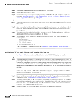
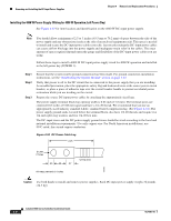
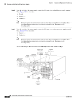
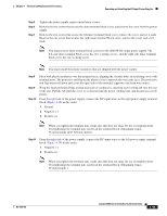
Removing and Installing the DC-Input Power Supplies Chapter 4 Removal and Replacement Procedures Installing the 4000 W Power Supply (Wiring for 4000 W Operation; Left Power Bay) See Figure 4-27 for item location and identification on the 4000 W DC-input power supply. Note You should allow a minimum of 2.5 to 3 inches (63.5 mm to 76.2 mm) of space between the side of the power supply and any obstructions (such as the side of an enclosed equipment rack). This space is needed to install and secure the DC-input power cables correctly. Incorrectly routing the DC-input power cables can cause airflow blockage into the power supply and inadequate strain relief in the cables. The exact amount of space required depends upon the gauge and flexibility of the DC-input power cables you are using. Follow these steps to install a 4000 W DC-input power supply wired for 4000 W operation and installed in the left power bay (POWER 1): Step 1 Step 2 Step 3 Ensure that the system (earth) ground connection has been made. For ground connection installation instructions, see the "Establishing the System Ground" section on page 3-22. Verify that power is off to the DC circuit that is connected to the power supply that you are installing. As an added precaution, place the appropriate safety flag and lockout devices at the source power circuit breaker, or place a piece of adhesive tape over the circuit breaker handle to prevent accidental power restoration while you are working on the circuit. Prepare the source DC-input power cables by attaching the appropriately sized lugs. The power supply terminal block lug opening width is 0.62 inch (15.8 mm). The terminal posts are centered 0.63 inches (15.88 mm) apart and have a 1/4-20 thread. We recommend that you use an appropriately sized industry standard 2-hole, standard barrel compression lug. (See Figure 4-34.) The power supply ground studs, located below the terminal block, also have 1/4-20 threads and require two 1/4-inch split-ring washers and two 1/4-20 hex nuts. The DC-input wires and the DC power supply ground wires should be sized according to the local and national installation requirements. Use only copper wire. For North American installations, use 90°C-rated, fine-strand copper conductors. Figure 4-34 DC Power Cable Lug 2.25 Ø .267 2 holes .25 .63 .37 All measurements in inches Crimp area 120563 Caution Use both hands to install and remove power supplies. Each DC-input power supply weighs 32 pounds (14.5 kg). 4-44 Catalyst 6500 Series Switches Installation Guide OL-5781-04
-
 1
1 -
2
-
3
-
4
-
5
-
6
-
7
-
8
-
9
-
10
-
11
-
12
-
13
-
14
-
15
-
16
-
17
-
18
-
19
-
20
-
21
-
22
-
23
-
24
-
25
-
26
-
27
-
28
-
29
-
30
-
31
-
32
-
33
-
34
-
35
-
36
-
37
-
38
-
39
-
40
-
41
-
42
-
43
-
44
-
45
-
46
-
47
-
48
-
49
-
50
-
51
-
52
-
53
-
54
-
55
-
56
-
57
-
58
-
59
-
60
-
61
-
62
-
63
-
64
-
65
-
66
-
67
-
68
-
69
-
70
-
71
-
72
-
73
-
74
-
75
-
76
-
77
-
78
-
79
-
80
-
81
-
82
-
83
-
84
-
85
-
86
-
87
-
88
-
89
-
90
-
91
-
92
-
93
-
94
-
95
-
96
-
97
-
98
-
99
-
100
-
101
-
102
-
103
-
104
-
105
-
106
-
107
-
108
-
109
-
110
-
111
-
112
-
113
-
114
-
115
-
116
-
117
-
118
-
119
-
120
-
121
-
122
-
123
-
124
-
125
-
126
-
127
-
128
-
129
-
130
-
131
-
132
-
133
-
134
-
135
-
136
-
137
-
138
-
139
-
140
-
141
-
142
-
143
-
144
-
145
-
146
-
147
-
148
-
149
-
150
-
151
-
152
-
153
-
154
-
155
-
156
-
157
-
158
-
159
-
160
-
161
-
162
-
163
-
164
-
165
-
166
-
167
-
168
-
169
-
170
-
171
-
172
-
173
-
174
-
175
-
176
-
177
-
178
-
 179
179 -
 180
180 -
 181
181 -
 182
182 -
 183
183 -
 184
184 -
 185
185 -
 186
186 -
 187
187 -
 188
188 -
 189
189 -
190
-
191
-
192
-
193
-
194
-
195
-
196
-
197
-
198
-
199
-
200
-
201
-
202
-
203
-
204
-
205
-
206
-
207
-
208
-
209
-
210
-
211
-
212
-
213
-
214
-
215
-
216
-
217
-
218
-
219
-
220
-
221
-
222
-
223
-
224
-
225
-
226
-
227
-
228
-
229
-
230
-
231
-
232
-
233
-
234
-
235
-
236
-
237
-
238
-
239
-
240
-
241
-
242
-
243
-
244
-
245
-
246
-
247
-
248
-
249
-
250
-
251
-
252
-
253
-
254
-
255
-
256
-
257
-
258
-
259
-
260
-
261
-
262
-
263
-
264
-
265
-
266
-
267
-
268
-
269
-
270
-
271
-
272
-
273
-
274
-
275
-
276
-
277
-
278
-
279
-
280
-
281
-
282
-
283
-
284
-
285
-
286
-
287
-
288
-
289
-
290
-
291
-
292
-
293
-
294
-
295
-
296
-
297
-
298
-
299
-
300
-
301
-
302
-
303
-
304
-
305
-
306
-
307
-
308
-
309
-
310
-
311
-
312
-
313
-
314
-
315
-
316
-
317
-
318
-
319
-
320
-
321
-
322
-
323
-
324
-
325
-
326
-
327
-
328
-
329
-
330
-
331
-
332
-
333
-
334
-
335
-
336
 |
 |