Cisco 6509 Installation Guide - Page 163
Identifying Startup Problems on E-3
 |
UPC - 746320196077
View all Cisco 6509 manuals
Add to My Manuals
Save this manual to your list of manuals |
Page 163 highlights
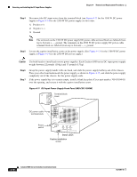
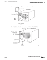
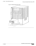
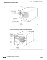
Chapter 4 Removal and Replacement Procedures Removing and Installing the DC-Input Power Supplies Step 7 Attach the appropriate lugs to the DC-input wires. The maximum width of a lug is 0.300 inch (7.6 mm). Note The wire should be sized according to local and national installation requirements and electrical codes. Use only copper wire. For North American installations of 2500 WDC-input power supplies, use fine-stranded copper conductors rated for 90°C. Step 8 Connect the DC-input wires to the terminal block (see Figure 4-16 for the 1300 W DC power supply or Figure 4-17 for the 2500 W DC power supply) in this order: 1. Ground 2. Negative (-) 3. Positive (+) Note The terminals on the 1300 W DC power supply DC power cable terminal block are labeled (from top to bottom) +, -, ground. The terminals on the 2500 W DC power supply DC power cable terminal block are labeled (from top to bottom) -, +, ground. Step 9 After ensuring that all wire connections are secure, reinstall the terminal block cover. Caution To prevent a short circuit or shock hazard after wiring the DC-input power supply, you must reinstall the terminal block cover. Caution In a system with dual power supplies, connect each power supply to a separate power source. In case of a power source failure to one supply, the second power source should still be available. Step 10 Step 11 Step 12 Remove any safety flag and lockout devices or any tape from the circuit breaker switch handle, and restore power by moving the circuit breaker switch handle to the On (|) position. Turn the power switch to the On (|) position on the power supply. Turning on the power switch also engages a pawl that locks the power supply in the chassis. Verify the power supply operation by ensuring that the power supply front panel LEDs are in these states: • INPUT OK LED is green • FAN OK LED is green • OUTPUT FAIL LED is not lit If the LEDs indicate a power problem, see the "Identifying Startup Problems" section on page E-3. OL-5781-04 Catalyst 6500 Series Switches Installation Guide 4-23
-
 1
1 -
2
-
3
-
4
-
5
-
6
-
7
-
8
-
9
-
10
-
11
-
12
-
13
-
14
-
15
-
16
-
17
-
18
-
19
-
20
-
21
-
22
-
23
-
24
-
25
-
26
-
27
-
28
-
29
-
30
-
31
-
32
-
33
-
34
-
35
-
36
-
37
-
38
-
39
-
40
-
41
-
42
-
43
-
44
-
45
-
46
-
47
-
48
-
49
-
50
-
51
-
52
-
53
-
54
-
55
-
56
-
57
-
58
-
59
-
60
-
61
-
62
-
63
-
64
-
65
-
66
-
67
-
68
-
69
-
70
-
71
-
72
-
73
-
74
-
75
-
76
-
77
-
78
-
79
-
80
-
81
-
82
-
83
-
84
-
85
-
86
-
87
-
88
-
89
-
90
-
91
-
92
-
93
-
94
-
95
-
96
-
97
-
98
-
99
-
100
-
101
-
102
-
103
-
104
-
105
-
106
-
107
-
108
-
109
-
110
-
111
-
112
-
113
-
114
-
115
-
116
-
117
-
118
-
119
-
120
-
121
-
122
-
123
-
124
-
125
-
126
-
127
-
128
-
129
-
130
-
131
-
132
-
133
-
134
-
135
-
136
-
137
-
138
-
139
-
140
-
141
-
142
-
143
-
144
-
145
-
146
-
147
-
148
-
149
-
150
-
151
-
152
-
153
-
154
-
155
-
156
-
157
-
 158
158 -
 159
159 -
 160
160 -
 161
161 -
 162
162 -
 163
163 -
 164
164 -
 165
165 -
 166
166 -
 167
167 -
 168
168 -
169
-
170
-
171
-
172
-
173
-
174
-
175
-
176
-
177
-
178
-
179
-
180
-
181
-
182
-
183
-
184
-
185
-
186
-
187
-
188
-
189
-
190
-
191
-
192
-
193
-
194
-
195
-
196
-
197
-
198
-
199
-
200
-
201
-
202
-
203
-
204
-
205
-
206
-
207
-
208
-
209
-
210
-
211
-
212
-
213
-
214
-
215
-
216
-
217
-
218
-
219
-
220
-
221
-
222
-
223
-
224
-
225
-
226
-
227
-
228
-
229
-
230
-
231
-
232
-
233
-
234
-
235
-
236
-
237
-
238
-
239
-
240
-
241
-
242
-
243
-
244
-
245
-
246
-
247
-
248
-
249
-
250
-
251
-
252
-
253
-
254
-
255
-
256
-
257
-
258
-
259
-
260
-
261
-
262
-
263
-
264
-
265
-
266
-
267
-
268
-
269
-
270
-
271
-
272
-
273
-
274
-
275
-
276
-
277
-
278
-
279
-
280
-
281
-
282
-
283
-
284
-
285
-
286
-
287
-
288
-
289
-
290
-
291
-
292
-
293
-
294
-
295
-
296
-
297
-
298
-
299
-
300
-
301
-
302
-
303
-
304
-
305
-
306
-
307
-
308
-
309
-
310
-
311
-
312
-
313
-
314
-
315
-
316
-
317
-
318
-
319
-
320
-
321
-
322
-
323
-
324
-
325
-
326
-
327
-
328
-
329
-
330
-
331
-
332
-
333
-
334
-
335
-
336
 |
 |
