Cisco 6509 Installation Guide - Page 303
Cleaning the Fiber Optic Connectors
 |
UPC - 746320196077
View all Cisco 6509 manuals
Add to My Manuals
Save this manual to your list of manuals |
Page 303 highlights
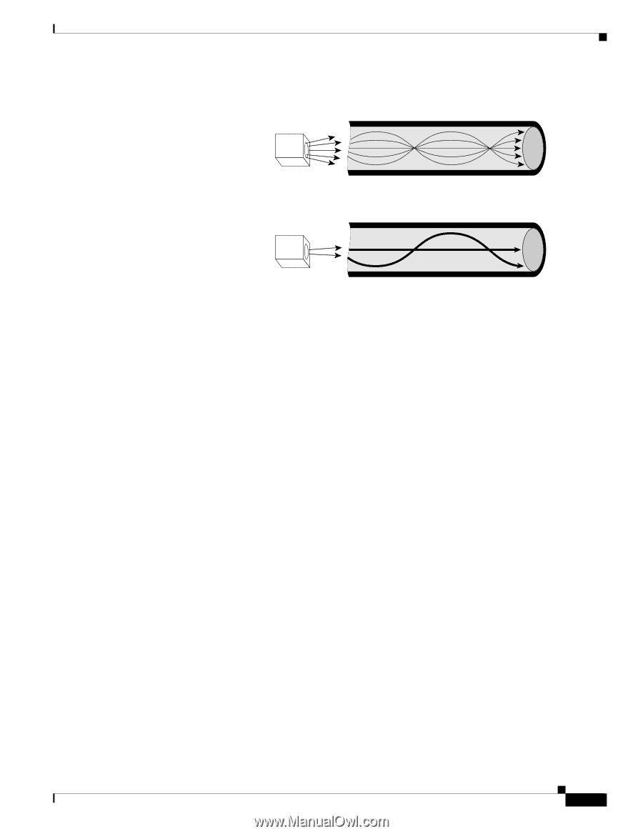
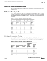
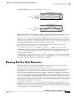
Appendix B Transceivers, Module Connectors, and Cable Specifications Cleaning the Fiber Optic Connectors Figure B-21 LED Transmission Compared to Laser Transmission LED transmission LED Laser Laser transmission 12871 Lasers launch light in a more concentrated fashion. A laser transmitter couples light into only a fraction of the existing modes or optical pathways present in the fiber-optic cable. (See Figure B-21.) The solution is to condition the laser light launched from the source (transmitter) so that it spreads the light evenly across the diameter of the fiber-optic cable making the launch look more like an LED source to the cable. The objective is to scramble the modes of light to distribute the power more equally in all modes and prevent the light from being concentrated in just a few modes. An unconditioned launch, in the worst case, might concentrate all of its light in the center of the fiber-optic cable, exciting only two or more modes equally. A significant variation in the amount of DMD is produced from one MMF cable to the next. No reasonable test can be performed to survey an installed cable plant to assess the effect of DMD, so you must use the mode-conditioning patch cords for all uplink modules using MMF when the link span exceeds 984 feet (300 meters). For link spans less than 984 feet (300 meters), you can omit the patch cord. (We do not recommend using the LX/LH GBIC and MMF without a patch cord for very short link distances of 33 to 328 feet [10 to 100 meters]. The result could be an elevated bit error rate [BER].) Cleaning the Fiber Optic Connectors Fiber optic connectors are used to connect two fibers together. When these connectors are used in a communications system, proper connection becomes a critical factor. Fiber optic cable connectors can be damaged by improper cleaning and connection procedures. Dirty or damaged fiber optic connectors can result in communication that is not repeatable or inaccurate. Fiber optic connectors differ from electrical or microwave connectors. In a fiber optic system, light is transmitted through an extremely small fiber core. Because fiber cores are often 62.5 microns or less in diameter, and dust particles range from a tenth of a micron to several microns in diameter, dust and any contamination at the end of the fiber core can degrade the performance of the connector interface where the two cores meet. Therefore, the connector must be precisely aligned, and the connector interface must be absolutely free of trapped foreign material. Connector loss, or insertion loss, is a critical performance characteristic of a fiber optic connector. Return loss is also an important factor. Return loss specifies the amount of reflected light; the lower the reflection, the better the connection. The best physical contact connectors have return losses greater than -40 dB, although -20 to -30 dB is more common. OL-5781-04 Catalyst 6500 Series Switches Installation Guide B-31
-
 1
1 -
2
-
3
-
4
-
5
-
6
-
7
-
8
-
9
-
10
-
11
-
12
-
13
-
14
-
15
-
16
-
17
-
18
-
19
-
20
-
21
-
22
-
23
-
24
-
25
-
26
-
27
-
28
-
29
-
30
-
31
-
32
-
33
-
34
-
35
-
36
-
37
-
38
-
39
-
40
-
41
-
42
-
43
-
44
-
45
-
46
-
47
-
48
-
49
-
50
-
51
-
52
-
53
-
54
-
55
-
56
-
57
-
58
-
59
-
60
-
61
-
62
-
63
-
64
-
65
-
66
-
67
-
68
-
69
-
70
-
71
-
72
-
73
-
74
-
75
-
76
-
77
-
78
-
79
-
80
-
81
-
82
-
83
-
84
-
85
-
86
-
87
-
88
-
89
-
90
-
91
-
92
-
93
-
94
-
95
-
96
-
97
-
98
-
99
-
100
-
101
-
102
-
103
-
104
-
105
-
106
-
107
-
108
-
109
-
110
-
111
-
112
-
113
-
114
-
115
-
116
-
117
-
118
-
119
-
120
-
121
-
122
-
123
-
124
-
125
-
126
-
127
-
128
-
129
-
130
-
131
-
132
-
133
-
134
-
135
-
136
-
137
-
138
-
139
-
140
-
141
-
142
-
143
-
144
-
145
-
146
-
147
-
148
-
149
-
150
-
151
-
152
-
153
-
154
-
155
-
156
-
157
-
158
-
159
-
160
-
161
-
162
-
163
-
164
-
165
-
166
-
167
-
168
-
169
-
170
-
171
-
172
-
173
-
174
-
175
-
176
-
177
-
178
-
179
-
180
-
181
-
182
-
183
-
184
-
185
-
186
-
187
-
188
-
189
-
190
-
191
-
192
-
193
-
194
-
195
-
196
-
197
-
198
-
199
-
200
-
201
-
202
-
203
-
204
-
205
-
206
-
207
-
208
-
209
-
210
-
211
-
212
-
213
-
214
-
215
-
216
-
217
-
218
-
219
-
220
-
221
-
222
-
223
-
224
-
225
-
226
-
227
-
228
-
229
-
230
-
231
-
232
-
233
-
234
-
235
-
236
-
237
-
238
-
239
-
240
-
241
-
242
-
243
-
244
-
245
-
246
-
247
-
248
-
249
-
250
-
251
-
252
-
253
-
254
-
255
-
256
-
257
-
258
-
259
-
260
-
261
-
262
-
263
-
264
-
265
-
266
-
267
-
268
-
269
-
270
-
271
-
272
-
273
-
274
-
275
-
276
-
277
-
278
-
279
-
280
-
281
-
282
-
283
-
284
-
285
-
286
-
287
-
288
-
289
-
290
-
291
-
292
-
293
-
294
-
295
-
296
-
297
-
 298
298 -
 299
299 -
 300
300 -
 301
301 -
 302
302 -
 303
303 -
 304
304 -
 305
305 -
 306
306 -
 307
307 -
 308
308 -
309
-
310
-
311
-
312
-
313
-
314
-
315
-
316
-
317
-
318
-
319
-
320
-
321
-
322
-
323
-
324
-
325
-
326
-
327
-
328
-
329
-
330
-
331
-
332
-
333
-
334
-
335
-
336
 |
 |