Cisco 6509 Installation Guide - Page 157
Removing and Installing a 1300 W or 2500 W DC-Input Power Supply
 |
UPC - 746320196077
View all Cisco 6509 manuals
Add to My Manuals
Save this manual to your list of manuals |
Page 157 highlights
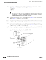
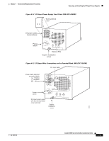
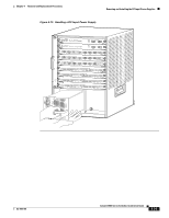
Chapter 4 Removal and Replacement Procedures Removing and Installing the DC-Input Power Supplies Removing and Installing a 1300 W or 2500 W DC-Input Power Supply This section covers the power supply removal and installation procedures for the 1300 W and the 2500 W DC-input power supplies and is divided into the following topics: • Required Tools, page 4-17 • Removing a 1300 W or 2500 W DC-Input Power Supply, page 4-17 • Installing a 1300 W or 2500 W DC-Input Power Supply, page 4-22 Required Tools Use a flat-blade or number 2 Phillips-head screwdriver to perform these procedures. You might also need cutters to cut any cable ties that are installed on the power supply. Removing a 1300 W or 2500 W DC-Input Power Supply Warning Before performing any of the following procedures, ensure that power is removed from the DC circuits. To ensure that all power is removed, locate the circuit breakers or fuses on the DC power lines that service the DC circuits. Turn OFF the DC power line circuit breakers and remove the DC power line fuses. Statement 322 Warning Hazardous voltage or energy is present on the backplane when the system is operating. Use caution when servicing. Statement 1034 Warning When installing or replacing the unit, the ground connection must always be made first and disconnected last. Statement 1046 To remove a DC-input power supply, follow these steps: Step 1 Step 2 Step 3 Verify that power is off to the DC circuit on the power supply that you are removing. As an added precaution, place the appropriate safety flag and lockout devices at the source power circuit breaker, or place a piece of adhesive tape over the circuit breaker handle to prevent accidental power restoration while you are working on the circuit. Turn the power switch to the Off (0) position on the power supply that you are removing. (See Figure 4-11 for the 1300 W DC power supply or Figure 4-12 for the 2500 W DC power supply.) Turning the power switch off also disengages a pawl that unlocks the power supply from the chassis. Remove the two screws securing the terminal block cover, and slide the cover off the terminal block. (See Figure 4-11 for the 1300 W DC power supply or Figure 4-12 for the 2500 W DC power supply.) OL-5781-04 Catalyst 6500 Series Switches Installation Guide 4-17
-
 1
1 -
2
-
3
-
4
-
5
-
6
-
7
-
8
-
9
-
10
-
11
-
12
-
13
-
14
-
15
-
16
-
17
-
18
-
19
-
20
-
21
-
22
-
23
-
24
-
25
-
26
-
27
-
28
-
29
-
30
-
31
-
32
-
33
-
34
-
35
-
36
-
37
-
38
-
39
-
40
-
41
-
42
-
43
-
44
-
45
-
46
-
47
-
48
-
49
-
50
-
51
-
52
-
53
-
54
-
55
-
56
-
57
-
58
-
59
-
60
-
61
-
62
-
63
-
64
-
65
-
66
-
67
-
68
-
69
-
70
-
71
-
72
-
73
-
74
-
75
-
76
-
77
-
78
-
79
-
80
-
81
-
82
-
83
-
84
-
85
-
86
-
87
-
88
-
89
-
90
-
91
-
92
-
93
-
94
-
95
-
96
-
97
-
98
-
99
-
100
-
101
-
102
-
103
-
104
-
105
-
106
-
107
-
108
-
109
-
110
-
111
-
112
-
113
-
114
-
115
-
116
-
117
-
118
-
119
-
120
-
121
-
122
-
123
-
124
-
125
-
126
-
127
-
128
-
129
-
130
-
131
-
132
-
133
-
134
-
135
-
136
-
137
-
138
-
139
-
140
-
141
-
142
-
143
-
144
-
145
-
146
-
147
-
148
-
149
-
150
-
151
-
 152
152 -
 153
153 -
 154
154 -
 155
155 -
 156
156 -
 157
157 -
 158
158 -
 159
159 -
 160
160 -
 161
161 -
 162
162 -
163
-
164
-
165
-
166
-
167
-
168
-
169
-
170
-
171
-
172
-
173
-
174
-
175
-
176
-
177
-
178
-
179
-
180
-
181
-
182
-
183
-
184
-
185
-
186
-
187
-
188
-
189
-
190
-
191
-
192
-
193
-
194
-
195
-
196
-
197
-
198
-
199
-
200
-
201
-
202
-
203
-
204
-
205
-
206
-
207
-
208
-
209
-
210
-
211
-
212
-
213
-
214
-
215
-
216
-
217
-
218
-
219
-
220
-
221
-
222
-
223
-
224
-
225
-
226
-
227
-
228
-
229
-
230
-
231
-
232
-
233
-
234
-
235
-
236
-
237
-
238
-
239
-
240
-
241
-
242
-
243
-
244
-
245
-
246
-
247
-
248
-
249
-
250
-
251
-
252
-
253
-
254
-
255
-
256
-
257
-
258
-
259
-
260
-
261
-
262
-
263
-
264
-
265
-
266
-
267
-
268
-
269
-
270
-
271
-
272
-
273
-
274
-
275
-
276
-
277
-
278
-
279
-
280
-
281
-
282
-
283
-
284
-
285
-
286
-
287
-
288
-
289
-
290
-
291
-
292
-
293
-
294
-
295
-
296
-
297
-
298
-
299
-
300
-
301
-
302
-
303
-
304
-
305
-
306
-
307
-
308
-
309
-
310
-
311
-
312
-
313
-
314
-
315
-
316
-
317
-
318
-
319
-
320
-
321
-
322
-
323
-
324
-
325
-
326
-
327
-
328
-
329
-
330
-
331
-
332
-
333
-
334
-
335
-
336
 |
 |
