Cisco 6509 Installation Guide - Page 240
Table A-13, W Power Supply Specifications
 |
UPC - 746320196077
View all Cisco 6509 manuals
Add to My Manuals
Save this manual to your list of manuals |
Page 240 highlights
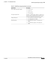
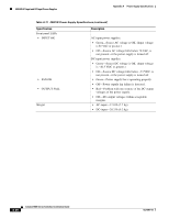
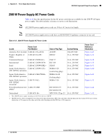
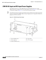
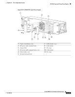
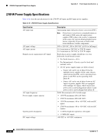
2700 W AC-Input and DC-Input Power Supplies Appendix A Power Supply Specifications 2700 W Power Supply Specifications Table A-11 lists the specifications for the 2700 W AC-input and DC-input power supplies. Table A-13 2700 W Power Supply Specifications Specification AC-input type AC-input voltage AC-input current Branch circuit requirement (AC-input) AC-input frequency Power supply output capacity System power dissipation DC-input voltage Description Autoranging input with power factor correction (PFC). Note Power factor correction is a standard feature on all Catalyst 6500 series AC-input power supplies. PFC reduces the reactive component in the source AC current allowing higher power factors (typically 99 percent or better) and lower harmonic current components. 100 to 120 VAC, 200 to 240 VAC (±10% for full range) 16 A maximum at 200 VAC at 2700 W output 16 A maximum at 100 VAC at 1350 W output Each chassis power supply should have its own dedicated, fused-branch circuit: • For North America-20 A • For International-Circuits sized to local and national codes • All AC power supply inputs are fully isolated. - Source AC can be out of phase between multiple power supplies in the same chassis, which means that PS1 can be operating from phase A and PS2 can be operating from phase B. - Source AC can be out of phase between AC inputs on power supplies that are equipped with multiple AC inputs, which means that power cord 1 can be plugged into phase A and power cord 2 can be plugged into phase B. 50/60 Hz (nominal) (±3% for full range) • 1350 W maximum (100-120 VAC) • 2700 W maximum (200-240 VAC) • 1350 W maximum (-48 to -60 VDC, with one DC input) • 2700 W maximum (-48 to -60 VDC, with two DC inputs) • 3.4 KVA (high-line operation; AC-input) • 3.5 KW (DC-input) -48 VDC to -60 VDC continuous A-30 Catalyst 6500 Series Switches Installation Guide OL-5781-04
-
 1
1 -
2
-
3
-
4
-
5
-
6
-
7
-
8
-
9
-
10
-
11
-
12
-
13
-
14
-
15
-
16
-
17
-
18
-
19
-
20
-
21
-
22
-
23
-
24
-
25
-
26
-
27
-
28
-
29
-
30
-
31
-
32
-
33
-
34
-
35
-
36
-
37
-
38
-
39
-
40
-
41
-
42
-
43
-
44
-
45
-
46
-
47
-
48
-
49
-
50
-
51
-
52
-
53
-
54
-
55
-
56
-
57
-
58
-
59
-
60
-
61
-
62
-
63
-
64
-
65
-
66
-
67
-
68
-
69
-
70
-
71
-
72
-
73
-
74
-
75
-
76
-
77
-
78
-
79
-
80
-
81
-
82
-
83
-
84
-
85
-
86
-
87
-
88
-
89
-
90
-
91
-
92
-
93
-
94
-
95
-
96
-
97
-
98
-
99
-
100
-
101
-
102
-
103
-
104
-
105
-
106
-
107
-
108
-
109
-
110
-
111
-
112
-
113
-
114
-
115
-
116
-
117
-
118
-
119
-
120
-
121
-
122
-
123
-
124
-
125
-
126
-
127
-
128
-
129
-
130
-
131
-
132
-
133
-
134
-
135
-
136
-
137
-
138
-
139
-
140
-
141
-
142
-
143
-
144
-
145
-
146
-
147
-
148
-
149
-
150
-
151
-
152
-
153
-
154
-
155
-
156
-
157
-
158
-
159
-
160
-
161
-
162
-
163
-
164
-
165
-
166
-
167
-
168
-
169
-
170
-
171
-
172
-
173
-
174
-
175
-
176
-
177
-
178
-
179
-
180
-
181
-
182
-
183
-
184
-
185
-
186
-
187
-
188
-
189
-
190
-
191
-
192
-
193
-
194
-
195
-
196
-
197
-
198
-
199
-
200
-
201
-
202
-
203
-
204
-
205
-
206
-
207
-
208
-
209
-
210
-
211
-
212
-
213
-
214
-
215
-
216
-
217
-
218
-
219
-
220
-
221
-
222
-
223
-
224
-
225
-
226
-
227
-
228
-
229
-
230
-
231
-
232
-
233
-
234
-
 235
235 -
 236
236 -
 237
237 -
 238
238 -
 239
239 -
 240
240 -
 241
241 -
 242
242 -
 243
243 -
 244
244 -
 245
245 -
246
-
247
-
248
-
249
-
250
-
251
-
252
-
253
-
254
-
255
-
256
-
257
-
258
-
259
-
260
-
261
-
262
-
263
-
264
-
265
-
266
-
267
-
268
-
269
-
270
-
271
-
272
-
273
-
274
-
275
-
276
-
277
-
278
-
279
-
280
-
281
-
282
-
283
-
284
-
285
-
286
-
287
-
288
-
289
-
290
-
291
-
292
-
293
-
294
-
295
-
296
-
297
-
298
-
299
-
300
-
301
-
302
-
303
-
304
-
305
-
306
-
307
-
308
-
309
-
310
-
311
-
312
-
313
-
314
-
315
-
316
-
317
-
318
-
319
-
320
-
321
-
322
-
323
-
324
-
325
-
326
-
327
-
328
-
329
-
330
-
331
-
332
-
333
-
334
-
335
-
336
 |
 |
