Cisco 6509 Installation Guide - Page 198
Warning, Step 1, Step 2, Step 3, Caution, Step 4
 |
UPC - 746320196077
View all Cisco 6509 manuals
Add to My Manuals
Save this manual to your list of manuals |
Page 198 highlights
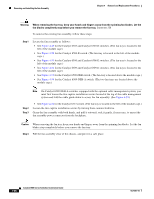
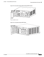
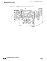
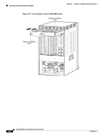
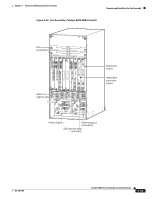
Removing and Installing the Fan Assembly Chapter 4 Removal and Replacement Procedures Warning When removing the fan tray, keep your hands and fingers away from the spinning fan blades. Let the fan blades completely stop before you remove the fan tray. Statement 258 To remove the existing fan assembly, follow these steps: Step 1 Locate the fan assembly as follows: • See Figure 4-49 for the Catalyst 6503 and Catalyst 6503-E switches. (The fan tray is located to the left of the module cage.) • See Figure 4-50 for the Catalyst 6504-E switch. (The fan tray is located to the left of the module cage.) • See Figure 4-51 for the Catalyst 6506 and Catalyst 6506-E switches. (The fan tray is located to the left of the module cage.) • See Figure 4-52 for the Catalyst 6509 and Catalyst 6509-E switches. (The fan tray is located to the left of the module cage.) • See Figure 4-53 for the Catalyst 6509-NEB switch. (The fan tray is located above the module cage.) • See Figure 4-54 for the Catalyst 6509-NEB-A switch. (The two fan trays are located above the module cage.) Note On Catalyst 6509-NEB-A switches equipped with the optional cable management system, you must first loosen the two captive installation screws located at the top of the cable management system and fold the cable guide down to access the fan assembly. (See Figure 4-55.) Step 2 Step 3 • See Figure 4-56 for the Catalyst 6513 switch. (The fan tray is located to the left of the module cage.) Loosen the two captive installation screws by turning them counterclockwise. Grasp the fan assembly with both hands, and pull it outward; rock it gently, if necessary, to unseat the fan assembly power connector from the backplane. Caution When removing the fan tray, keep your hands and fingers away from the spinning fan blades. Let the fan blades stop completely before you remove the fan tray. Step 4 Pull the fan assembly clear of the chassis, and put it in a safe place. 4-58 Catalyst 6500 Series Switches Installation Guide OL-5781-04
-
 1
1 -
2
-
3
-
4
-
5
-
6
-
7
-
8
-
9
-
10
-
11
-
12
-
13
-
14
-
15
-
16
-
17
-
18
-
19
-
20
-
21
-
22
-
23
-
24
-
25
-
26
-
27
-
28
-
29
-
30
-
31
-
32
-
33
-
34
-
35
-
36
-
37
-
38
-
39
-
40
-
41
-
42
-
43
-
44
-
45
-
46
-
47
-
48
-
49
-
50
-
51
-
52
-
53
-
54
-
55
-
56
-
57
-
58
-
59
-
60
-
61
-
62
-
63
-
64
-
65
-
66
-
67
-
68
-
69
-
70
-
71
-
72
-
73
-
74
-
75
-
76
-
77
-
78
-
79
-
80
-
81
-
82
-
83
-
84
-
85
-
86
-
87
-
88
-
89
-
90
-
91
-
92
-
93
-
94
-
95
-
96
-
97
-
98
-
99
-
100
-
101
-
102
-
103
-
104
-
105
-
106
-
107
-
108
-
109
-
110
-
111
-
112
-
113
-
114
-
115
-
116
-
117
-
118
-
119
-
120
-
121
-
122
-
123
-
124
-
125
-
126
-
127
-
128
-
129
-
130
-
131
-
132
-
133
-
134
-
135
-
136
-
137
-
138
-
139
-
140
-
141
-
142
-
143
-
144
-
145
-
146
-
147
-
148
-
149
-
150
-
151
-
152
-
153
-
154
-
155
-
156
-
157
-
158
-
159
-
160
-
161
-
162
-
163
-
164
-
165
-
166
-
167
-
168
-
169
-
170
-
171
-
172
-
173
-
174
-
175
-
176
-
177
-
178
-
179
-
180
-
181
-
182
-
183
-
184
-
185
-
186
-
187
-
188
-
189
-
190
-
191
-
192
-
 193
193 -
 194
194 -
 195
195 -
 196
196 -
 197
197 -
 198
198 -
 199
199 -
 200
200 -
 201
201 -
 202
202 -
 203
203 -
204
-
205
-
206
-
207
-
208
-
209
-
210
-
211
-
212
-
213
-
214
-
215
-
216
-
217
-
218
-
219
-
220
-
221
-
222
-
223
-
224
-
225
-
226
-
227
-
228
-
229
-
230
-
231
-
232
-
233
-
234
-
235
-
236
-
237
-
238
-
239
-
240
-
241
-
242
-
243
-
244
-
245
-
246
-
247
-
248
-
249
-
250
-
251
-
252
-
253
-
254
-
255
-
256
-
257
-
258
-
259
-
260
-
261
-
262
-
263
-
264
-
265
-
266
-
267
-
268
-
269
-
270
-
271
-
272
-
273
-
274
-
275
-
276
-
277
-
278
-
279
-
280
-
281
-
282
-
283
-
284
-
285
-
286
-
287
-
288
-
289
-
290
-
291
-
292
-
293
-
294
-
295
-
296
-
297
-
298
-
299
-
300
-
301
-
302
-
303
-
304
-
305
-
306
-
307
-
308
-
309
-
310
-
311
-
312
-
313
-
314
-
315
-
316
-
317
-
318
-
319
-
320
-
321
-
322
-
323
-
324
-
325
-
326
-
327
-
328
-
329
-
330
-
331
-
332
-
333
-
334
-
335
-
336
 |
 |