Cisco 6509 Installation Guide - Page 205
Installing the Fan Assembly, Checking the Installation
 |
UPC - 746320196077
View all Cisco 6509 manuals
Add to My Manuals
Save this manual to your list of manuals |
Page 205 highlights
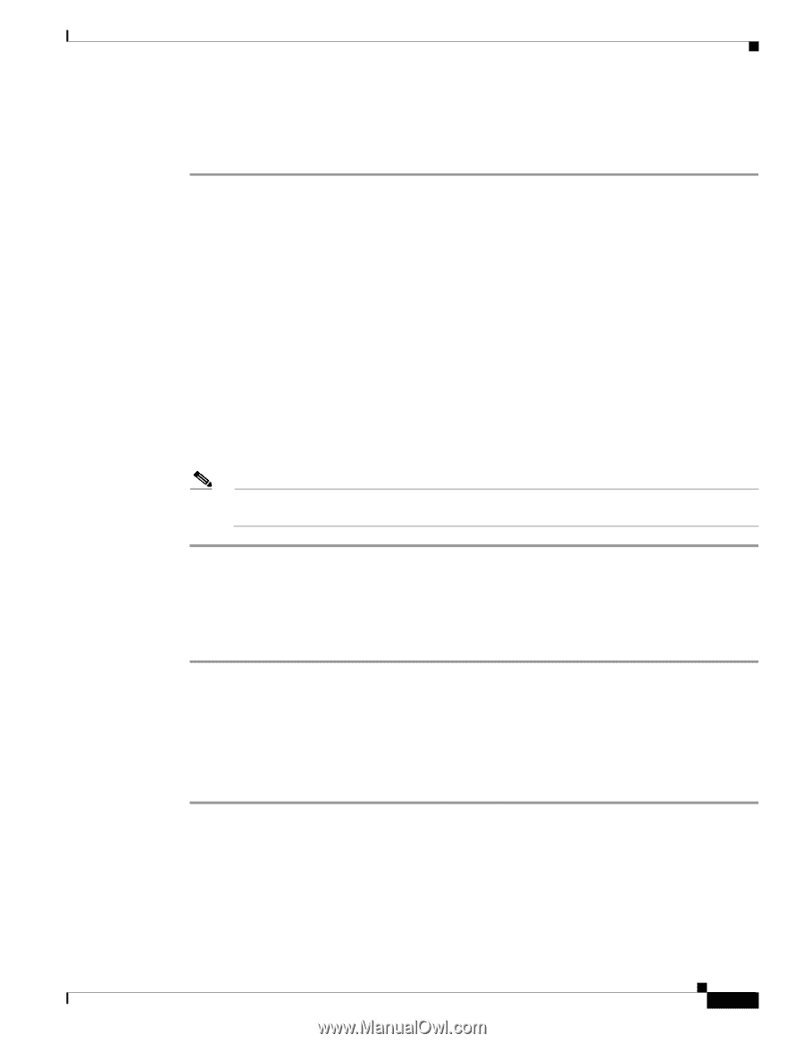
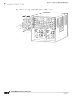
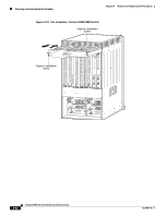
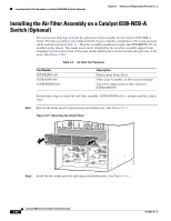
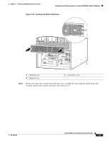
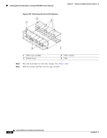
Chapter 4 Removal and Replacement Procedures Removing and Installing the Fan Assembly Installing the Fan Assembly To install the new fan assembly, follow these steps: Step 1 Step 2 Step 3 Step 4 Hold the fan assembly with the fans facing to the right and the FAN STATUS LED at the bottom. • See Figure 4-49 for the Catalyst 6503 and Catalyst 6503-E switches • See Figure 4-50 for the Catalyst 6504-E switch • See Figure 4-51 for the Catalyst 6506 and Catalyst 6506-E switches • See Figure 4-52 for the Catalyst 6509 and Catalyst 6509-E switches • See Figure 4-56 for the Catalyst 6513 switch For the Catalyst 6509-NEB switch, hold the fan assembly with the fans facing down and the FAN STATUS LED on the left. (See Figure 4-53.) For the Catalyst 6509-NEB-A switch, hold the fan assembly so that the handle is at the top of the assembly. (See Figure 4-54.) Place the fan assembly into the front chassis cavity so that it rests on the chassis, and then lift the fan assembly up slightly, aligning the top and bottom chassis guides. Push the fan assembly into the chassis until the power connector seats in the backplane and the captive installation screws make contact with the chassis. Tighten the captive installation screws. Note On the Catalyst 6509-NEB-A switch, fold the cable guide up, and tighten the two captive installation screws at the top of the chassis. (See Figure 4-55.) Checking the Installation To verify that the new fan assembly is installed correctly, follow these steps: Step 1 Step 2 Step 3 Listen for the fans; you should immediately hear them operating. If you do not hear them, ensure that the fan assembly is inserted completely in the chassis and that the faceplate is flush with the switch back panel. Verify that the FAN STATUS LED is green. If the LED is red, one or more of the fans are faulty. If after several attempts the fans do not operate or if you experience trouble with the installation (for instance, if the captive installation screws do not align with the chassis holes), contact a Cisco customer service representative for assistance. OL-5781-04 Catalyst 6500 Series Switches Installation Guide 4-65
-
 1
1 -
2
-
3
-
4
-
5
-
6
-
7
-
8
-
9
-
10
-
11
-
12
-
13
-
14
-
15
-
16
-
17
-
18
-
19
-
20
-
21
-
22
-
23
-
24
-
25
-
26
-
27
-
28
-
29
-
30
-
31
-
32
-
33
-
34
-
35
-
36
-
37
-
38
-
39
-
40
-
41
-
42
-
43
-
44
-
45
-
46
-
47
-
48
-
49
-
50
-
51
-
52
-
53
-
54
-
55
-
56
-
57
-
58
-
59
-
60
-
61
-
62
-
63
-
64
-
65
-
66
-
67
-
68
-
69
-
70
-
71
-
72
-
73
-
74
-
75
-
76
-
77
-
78
-
79
-
80
-
81
-
82
-
83
-
84
-
85
-
86
-
87
-
88
-
89
-
90
-
91
-
92
-
93
-
94
-
95
-
96
-
97
-
98
-
99
-
100
-
101
-
102
-
103
-
104
-
105
-
106
-
107
-
108
-
109
-
110
-
111
-
112
-
113
-
114
-
115
-
116
-
117
-
118
-
119
-
120
-
121
-
122
-
123
-
124
-
125
-
126
-
127
-
128
-
129
-
130
-
131
-
132
-
133
-
134
-
135
-
136
-
137
-
138
-
139
-
140
-
141
-
142
-
143
-
144
-
145
-
146
-
147
-
148
-
149
-
150
-
151
-
152
-
153
-
154
-
155
-
156
-
157
-
158
-
159
-
160
-
161
-
162
-
163
-
164
-
165
-
166
-
167
-
168
-
169
-
170
-
171
-
172
-
173
-
174
-
175
-
176
-
177
-
178
-
179
-
180
-
181
-
182
-
183
-
184
-
185
-
186
-
187
-
188
-
189
-
190
-
191
-
192
-
193
-
194
-
195
-
196
-
197
-
198
-
199
-
 200
200 -
 201
201 -
 202
202 -
 203
203 -
 204
204 -
 205
205 -
 206
206 -
 207
207 -
 208
208 -
 209
209 -
 210
210 -
211
-
212
-
213
-
214
-
215
-
216
-
217
-
218
-
219
-
220
-
221
-
222
-
223
-
224
-
225
-
226
-
227
-
228
-
229
-
230
-
231
-
232
-
233
-
234
-
235
-
236
-
237
-
238
-
239
-
240
-
241
-
242
-
243
-
244
-
245
-
246
-
247
-
248
-
249
-
250
-
251
-
252
-
253
-
254
-
255
-
256
-
257
-
258
-
259
-
260
-
261
-
262
-
263
-
264
-
265
-
266
-
267
-
268
-
269
-
270
-
271
-
272
-
273
-
274
-
275
-
276
-
277
-
278
-
279
-
280
-
281
-
282
-
283
-
284
-
285
-
286
-
287
-
288
-
289
-
290
-
291
-
292
-
293
-
294
-
295
-
296
-
297
-
298
-
299
-
300
-
301
-
302
-
303
-
304
-
305
-
306
-
307
-
308
-
309
-
310
-
311
-
312
-
313
-
314
-
315
-
316
-
317
-
318
-
319
-
320
-
321
-
322
-
323
-
324
-
325
-
326
-
327
-
328
-
329
-
330
-
331
-
332
-
333
-
334
-
335
-
336
 |
 |